
System for providing projected information combined with outside scenery

a projection system and projection system technology, applied in the field of projection systems, can solve the problems of reducing the image visibility of the current head-up and window display system, the need for powerful emitted light, and the strong ambient light, so as to improve the efficiency of the combined image, enhance the user's safety, and improve the effect of the combined imag

Active Publication Date: 2016-08-30
PEERI JONATHAN
View PDF11 Cites 21 Cited by
  • Summary
  • Abstract
  • Description
  • Claims
  • Application Information

AI Technical Summary

Benefits of technology

The patent is about a new system that improves the visibility of head-up and window display systems by operating under all light conditions, instead of relying on powerful emitted light. This system aims to provide better visibility, save cost and energy, and maintain a wide field of view and viewer motion. It also eliminates the need for expensive and complex optical elements, which reduces complexity and simplifies the manufacturing process.

Problems solved by technology

Current head-up and window display systems suffer from reduced image visibility in strong ambient light, and the need for powerful emitted light for generating an image.

Method used


Image

  • System for providing projected information combined with outside scenery
  • System for providing projected information combined with outside scenery
  • System for providing projected information combined with outside scenery

Examples


Embodiment Construction

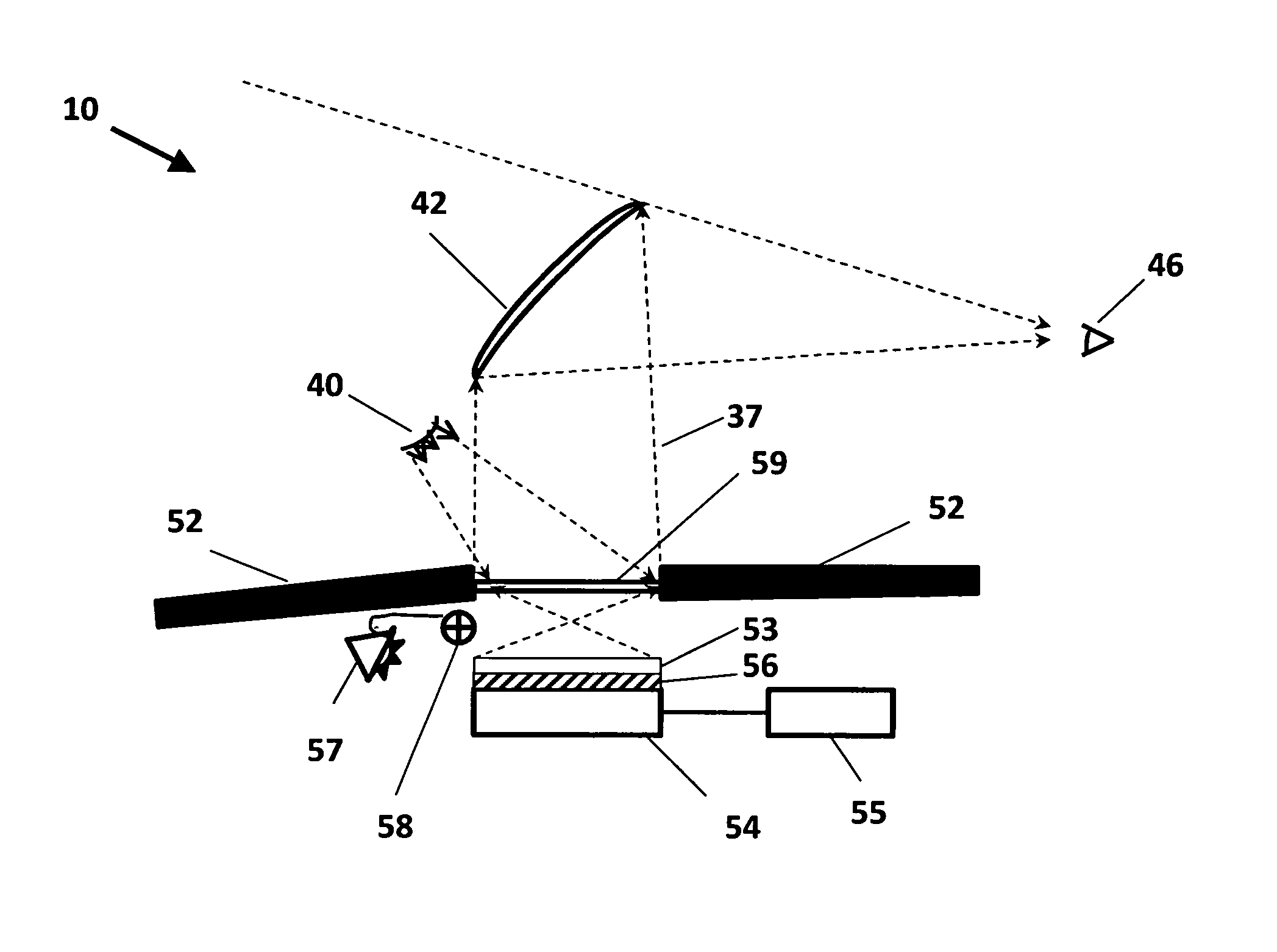
[0047]The best mode for carrying out the invention is presented in terms that disclose a preferred embodiment of a system, as shown in FIGS. 1-5, for producing a display image on a transparent or semi-transparent surface.

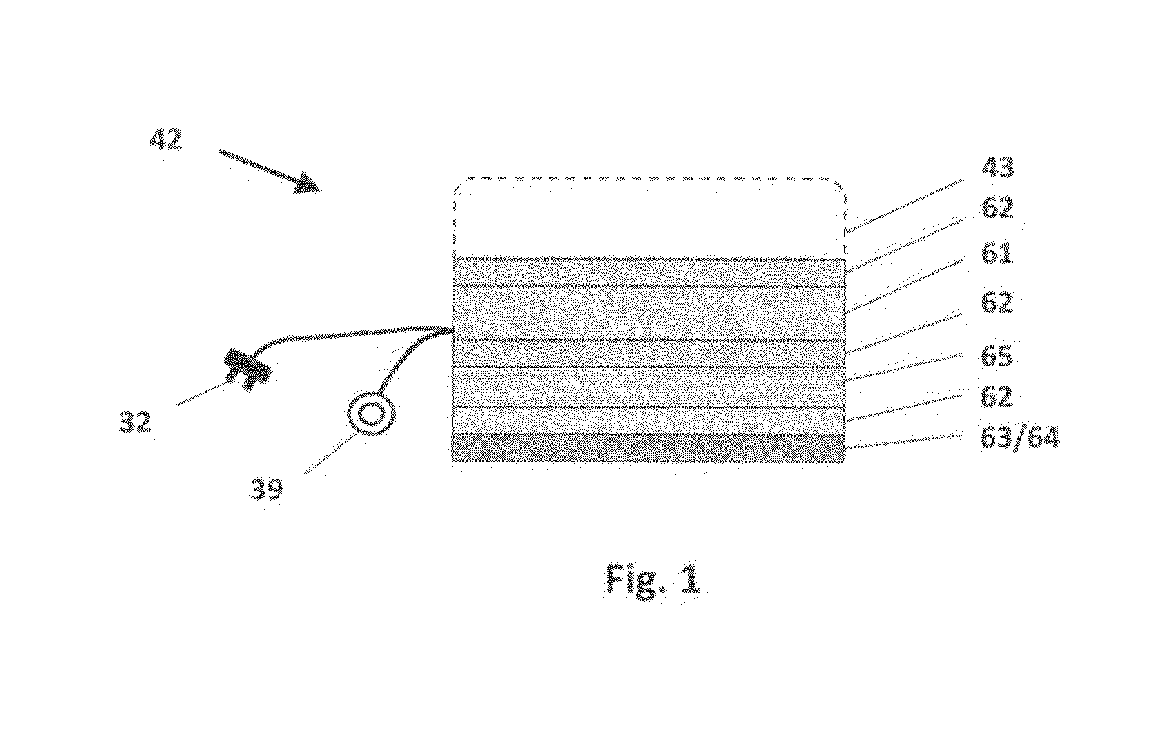
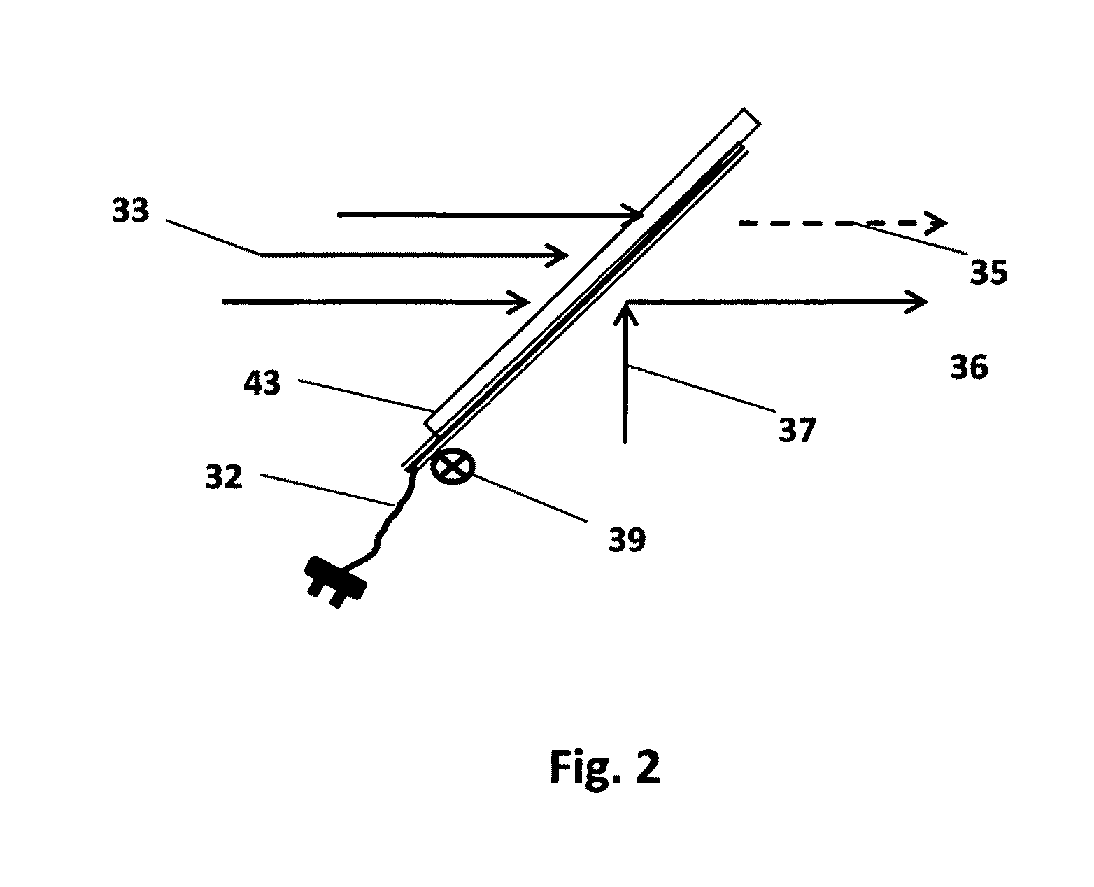
[0048]The system 10, as shown in FIG. 3, is comprised of two major elements: an inventive optical device (42), which is also referred to as a JaaZ optical Device™ (JOD), and a reflective display array (RDA) (50), as shown in FIG. 5.

[0049]The system disclosed herein typically pertains to reflective head-up display systems, which utilize ambient light (40) (Not part of system 10) as a major light source for creating a desired image. The ambient light shines on a reflective display device (RDD) (54), with or without a light collecting element (LCE) (59) and a polarized directing surface (53). The selected image elements (pixels) are reflected by a reflecting surface (56), generating a sub-image. The sub-image is then combined with outside scenery (22) by the JOD (42), ...


PUM


Abstract

A system for producing a display image on a transparent, semi-transparent or translucent surface, without the need for an integral light source. The system includes a reflective surface that utilizes external light to project the display image in a selectable direction. A light collecting element collects and directs ambient light to the reflective surface. A display processor creates the display image and transmits the image onto an optical device. The optical device that has a reflective polarizer accepts the projected display image. The optical device selectively reflects light of the projected display image, and while controlling the optical properties of the light from second direction it combines the projected display image with the light from the second direction.

Description

[0001]This application claims priority of Provisional Application No. 61 / 796,415 filed Nov. 10, 2012.TECHNICAL FIELD[0002]The invention generally pertains to projection systems, and more particularly to a system for producing a projected head-up display on a transparent or semi-transparent, stationary or a window type surface.BACKGROUND ART[0003]Imaging and projection systems are well known in the art. Examples of imaging and projecting systems include a head-up display (HUD) and window displays. These imaging and projecting systems produce a display image that is either natural or combined with an artificial image generated by an electronic system toward a person's eye. A head-up display is mounted on a platform or any type of mounting not attached to the viewer which is incapable of transparent viewing, meaning the display image is overlaid on the normally viewed scenery. The display image appears at a distance from the viewer, as if it is part of the normal scenery. The display i...

Claims


Application Information

Patent Timeline
IPC IPC(8): G02B27/14G02B27/01
CPCG02B27/0172G02B27/0101G02B2027/012G02B2027/0118
Inventor PEERI, JONATHAN
Owner PEERI JONATHAN
Learn More