Variability resistant circuit element and signal processing method

a circuit element and resistance technology, applied in the field of circuit elements, can solve the problems of sensitivity of cycle time to variations, affecting the operation of circuit elements, and affecting the operation of circuit elements, and achieve the effect of increasing overhead and excessive power consumption

Active Publication Date: 2016-08-16
NXP BV
View PDF19 Cites 1 Cited by
  • Summary
  • Abstract
  • Description
  • Claims
  • Application Information

AI Technical Summary

Benefits of technology

[0023]This circuit arrangement provides self-correcting variability tolerance. The circuit can adapt to the process variations and eliminate the usage of pessimistic design margins.
[0027]The invention thus avoids the need for increased guard bands on the timing margins to account for static and dynamic variations. These result in excessive power consumption and result in an increased area overhead.

Problems solved by technology

Technology scaling has caused an enormous increase in timing variations, making it difficult to predict the cycle time of microprocessors.
The sensitivity of cycle time to variations is a major bottleneck in achieving the maximum performance and for meeting power specifications of applications with energy constraints.
For example, abrupt changes in the switching patterns can cause large transients current in the power mesh system and results in VDD drop on certain die locations.
The traditional worst case corner analysis based methodology for the determination of cycle time is overly pessimistic.
Therefore, the added design margin represents an overly pessimistic very high total safety margin, which in turn results in chips failing the power specification.
The resultant die area with the traditional worst case design approach increases and also its capability to deal with dynamic variations is limited.
However, the effectiveness of these techniques is limited to deal with dynamic variations.
However, the usage of existing EDS circuits requires a feedback mechanism for tuning the supply lines or body bias voltages in case of Canary FFs and pipeline flushing, architecture replay or cycle stalling for Razor FFs.
This complicates the design effort, thereby making it less attractive for the low cost system on chip applications.
The canary flip flop technique can only predict the occurrence of timing errors but cannot guarantee the complete elimination.
The ability to deal with an abrupt workload dependent fluctuation is also limited these FFs.
The varying degree and nature of impact of VT mismatches, soft event upsets (SEU) error and ageing effects like NBTI on these two flip flops make this assumption precarious.
However, this is impractical for general sequential circuits, real time processors for energy limited applications.
The re-execution of instruction or architecture replay not only increases the power consumption but also impacts the processing throughput by increasing the instruction per cycle count.
This results in fluctuation of computational latency that can be difficult to tolerate in many real time signal processing applications.

Method used


Image

  • Variability resistant circuit element and signal processing method
  • Variability resistant circuit element and signal processing method
  • Variability resistant circuit element and signal processing method

Examples


Embodiment Construction

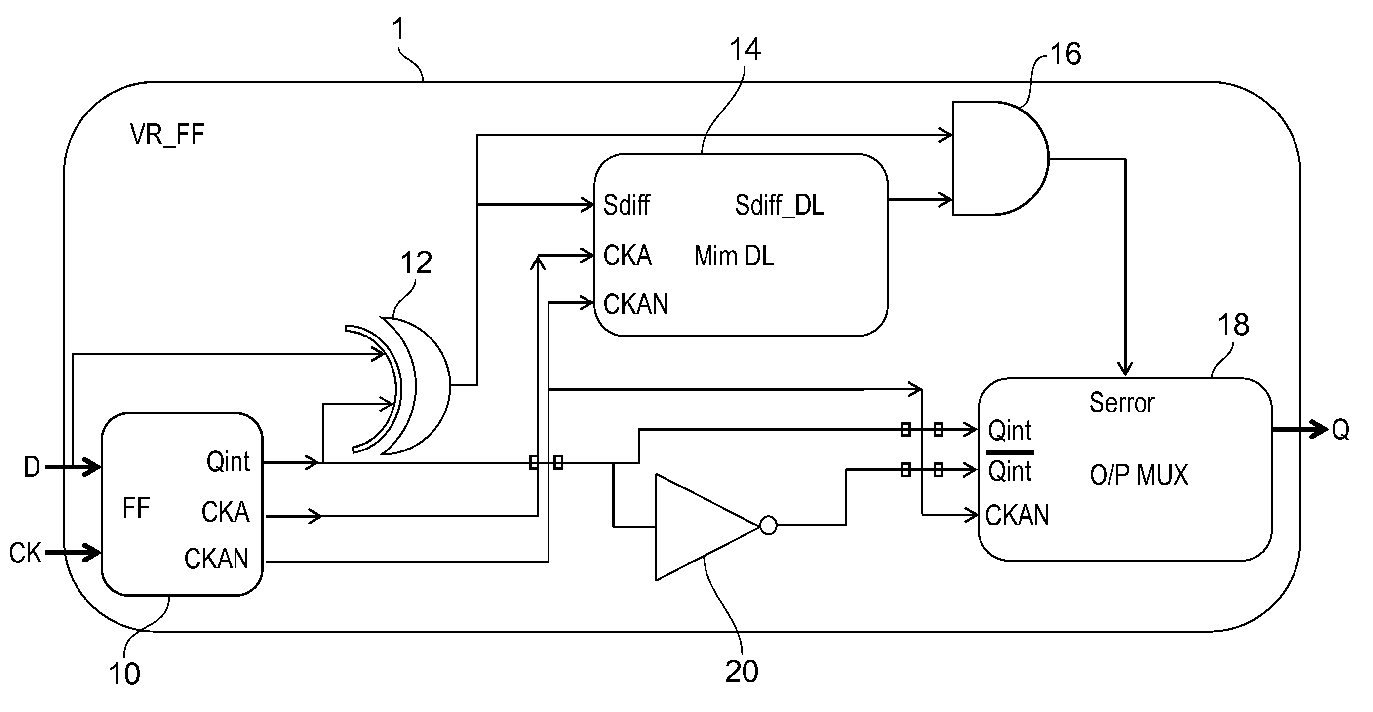
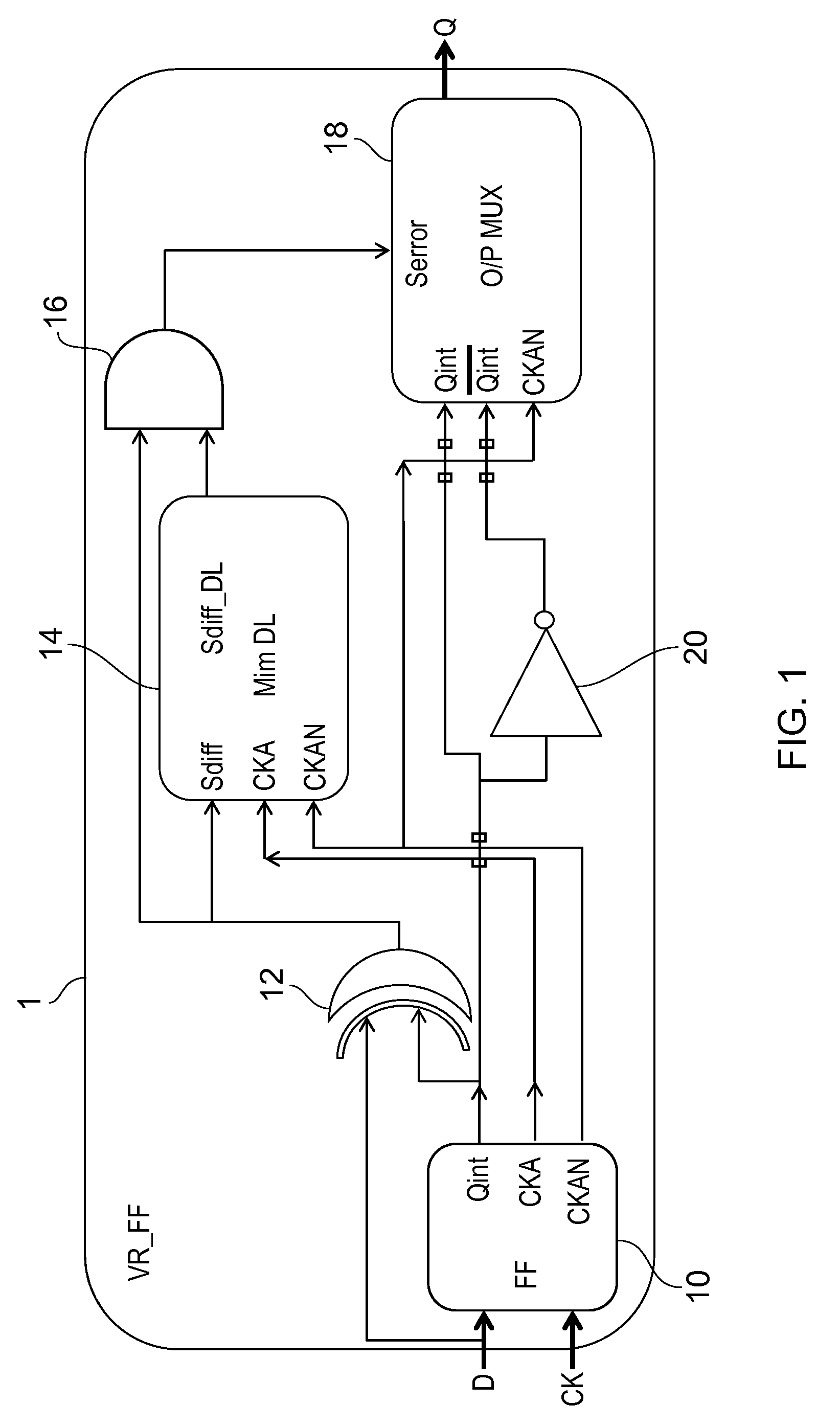
[0048]The invention provides a sequential circuit arrangement and method in which a latch input signal and a latched version of the input signal are compared to derive a difference signal. This difference signal can detect when changes in the input are not propagated to the output. A second logic gate arrangement derives an error signal from the difference signal and a delayed version of the difference signal. This means that normal operation of the circuit is not detected as an error—only when the latched output fails to follow the input after the normally expected delay is the error signal created. The latch element output or an inverted version of the latch element output is selected in dependence on the error signal.

[0049]FIG. 1 shows a circuit arrangement in accordance with one example of the invention.

[0050]The circuit is a sequential circuit 1, comprising a latch element 10 clocked by a clock input signal CK. It can be a regular flip flop which samples input data on the risin...


PUM


Abstract

A sequential circuit arrangement and method are provided in which a latch input signal and a latched version of the input signal are compared to derive a difference signal. This difference signal can detect when changes in the input are not propagated to the output. A second logic gate arrangement derives an error signal from the product of difference signal and a delayed version of the difference signal. This means that normal operation of the circuit is not detected as an error—only when the latched output fails to follow the input after the normally expected delay is the error signal created. The latch element output or an inverted version of the latch element output is selected in dependence on the error signal.

Description

CROSS-REFERENCE TO RELATED APPLICATIONS[0001]This application claims the priority under 35 U.S.C. §119 of European patent application no. 13186690.7, filed on Sep. 30, 2013, the contents of which are incorporated by reference herein.FIELD OF THE INVENTION[0002]This invention relates to circuit elements that are resilient to process variation and to method of processing signals to provide variability resilience.BACKGROUND OF THE INVENTION[0003]Technology scaling has caused an enormous increase in timing variations, making it difficult to predict the cycle time of microprocessors. The cycle time is determined by the target performance with an added timing margin, necessary for an acceptable yield. The sensitivity of cycle time to variations is a major bottleneck in achieving the maximum performance and for meeting power specifications of applications with energy constraints.[0004]The variations are classified into two categories; static variations like process variation and dynamic va...

Claims


Application Information

Patent Timeline
Patent Type & Authority Patents(United States)
IPC IPC(8): H03K3/00H03K3/037H03K3/356
CPCH03K3/0375H03K3/0372H03K3/356139H03K3/356156H03K3/356121
Inventor SHARMA, VIBHUPINEDA DE GYVEZ, JOSE DE JESUS
Owner NXP BV
Why Eureka
Try Eureka