Air conditioning device for vehicle

a technology for air conditioners and vehicles, applied in vehicle heating/cooling devices, vehicle components, transportation and packaging, etc., can solve the problems of insufficient solution of accumulator heat damage and inability to fully solve accumulator heat damage, etc., to shorten the connection path, suppress heat loss, and suppress heat loss

Active Publication Date: 2016-07-05
NISSAN MOTOR CO LTD
View PDF19 Cites 0 Cited by
  • Summary
  • Abstract
  • Description
  • Claims
  • Application Information

AI Technical Summary

Benefits of technology

[0007]In view of the problem described above, an objective of the present invention is to provide an air conditioner for a vehicle that is capable of protecting the accumulator tank from heat damage while suppressing heat loss by shortening the connection path between an external heat exchanger and an accumulator tank.
[0011]As described above, the external heat exchanger and the accumulator tank are disposed in positions near each other, for example, sandwiching a the front end of the side member 109, in an inside position and an outside position in the vehicle width direction. The connection path of a heat medium that connects the external heat exchanger and the accumulator tank thereby is shorter, suppressing heat loss.
[0012]The accumulator tank that is disposed in the front corner area is disposed separately from the external heat exchanger by the side member and is disposed separate from the front tire by the wheel house. Therefore, the side member and the wheel house become heat barrier walls that suppress the effect of heat from the external heat exchanger and the front tire, thereby protecting the accumulator tank from heat damage.
[0013]By configuring the arrangement of the accumulator tank with an attention to a space that is present near the external heat exchanger while having a side member and a wheel house as heat barrier walls in this manner, protecting the accumulator tank from heat damage while suppressing heat loss is possible by shortening the connection path between the external heat exchanger and the accumulator tank.

Problems solved by technology

In the prior art in which the accumulator tank is disposed in the lateral position of the condenser, the temperature of the surrounding environment increases temperature due to heat dissipation from the condenser; therefore, the accumulator is susceptible to heat damage.
Japanese Laid-Open Patent Application No. 1998-300283 discloses a concept in which an accumulator tank is fixed to a side frame; however, the positional relationship between the condenser and the accumulator tank is unclear, and the problem described above in which the accumulator tank is susceptible to heat damage is not fully solved.

Method used


Image

  • Air conditioning device for vehicle
  • Air conditioning device for vehicle
  • Air conditioning device for vehicle

Examples


embodiment 1

[0028]The configuration is described first.

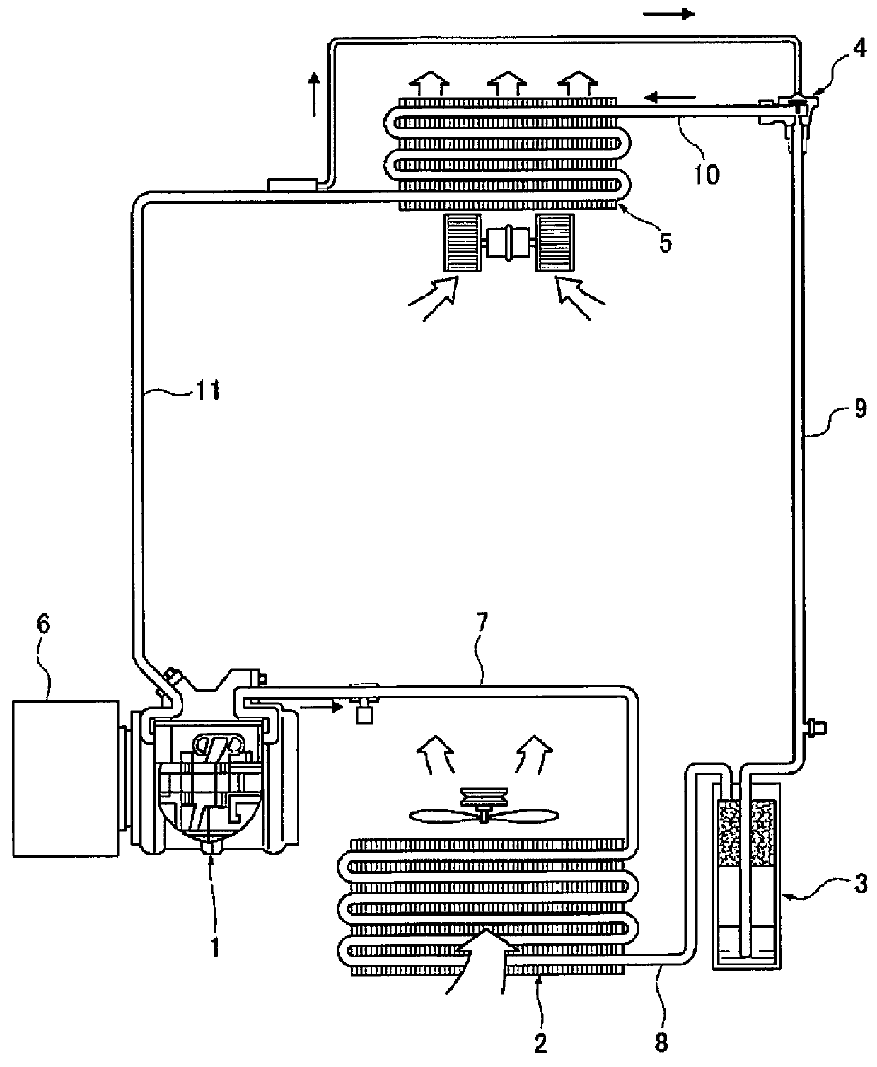
[0029]The “vehicle schematic configuration of the air conditioner for a vehicle,” the “circulation cycle configuration of the air conditioner for a vehicle,” and the “detailed arrangement of the configuration of the accumulator tank” will be separately described regarding the configuration of the first embodiment in the air conditioner for a vehicle.

[0030]Vehicle Schematic Configuration of the Air conditioner for a Vehicle

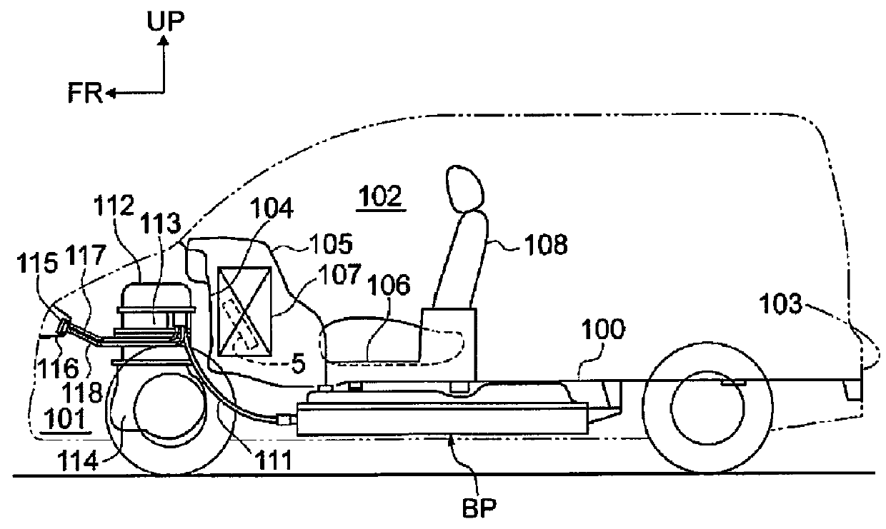
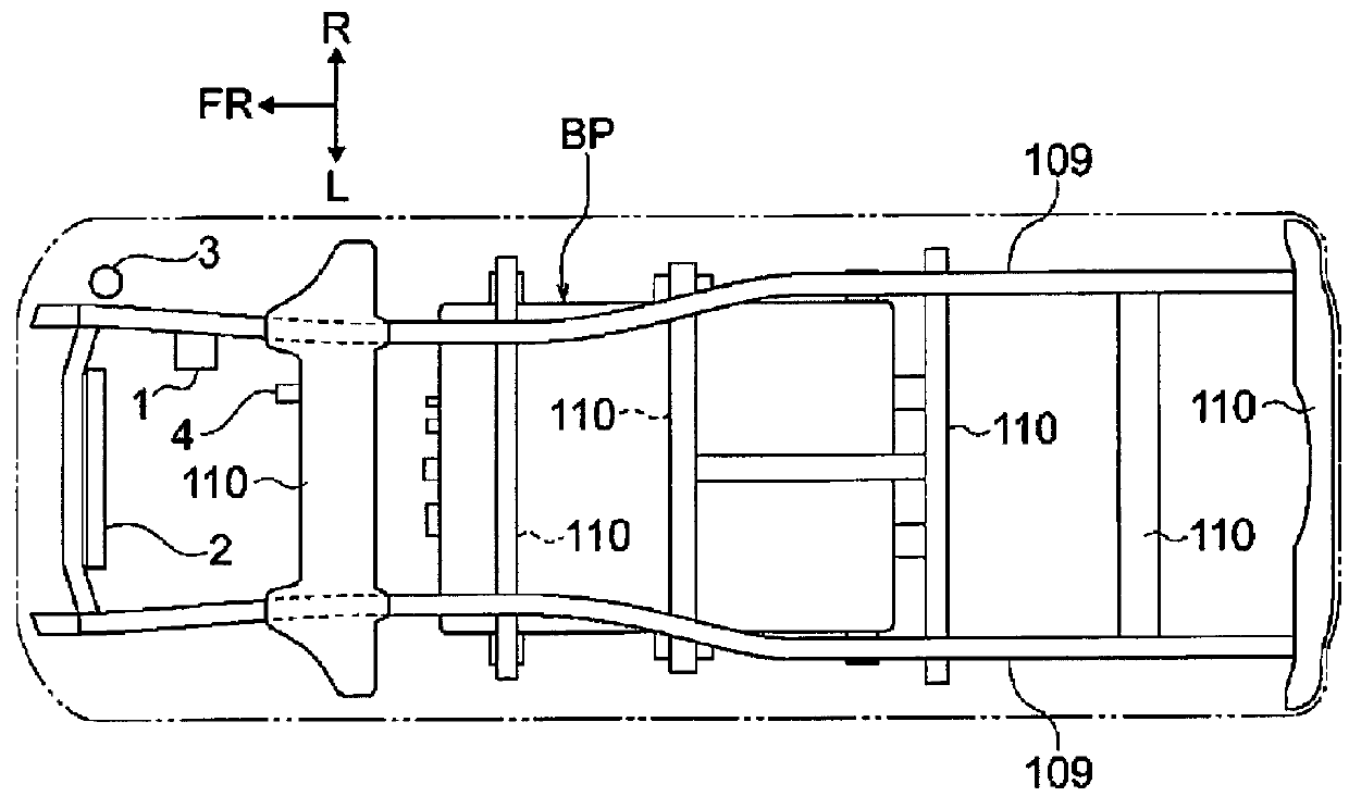
[0031]FIG. 1 and FIG. 2 illustrate a schematic configuration of a minivan-type electric automobile that is equipped with the air conditioner for a vehicle according to the first embodiment. The vehicle schematic configuration of the air conditioner for a vehicle will be described below based on FIG. 1 and FIG. 2.

[0032]In an electric automobile that is equipped with the air conditioner for a vehicle according to the first embodiment, a battery pack BP is disposed in the central position of the wheel base below a vehicle bod...


PUM


Abstract

An external heat exchanger and the accumulator tank are disposed in the circulation path of a heat medium. In the air conditioner for a vehicle, the external heat exchanger is disposed in a sideways position between member front ends of a pair of left and right side members, extending in the vehicle longitudinal direction, with the heat-exchanging surface facing forward in the vehicle. The accumulator tank is disposed in a front corner area that is formed in a position that is to the outside in the vehicle width direction from the member front end of one side member of the pair of left and right side members, and that is in front of a vehicle wheel house covering a front tire.

Description

CROSS-REFERENCE TO RELATED APPLICATIONS[0001]This application is a U.S. National stage application of International Application No. PCT / JP2013 / 066118 filed, Jun. 11, 2013, which claims priority to Japanese Patent Application No. 2012-153494 filed in Japan on Jul. 9, 2012, the contents of each of which are hereby incorporated herein by reference.BACKGROUND[0002]1. Field of the Invention[0003]The present invention relates to an air conditioner for a vehicle having an accumulator tank for performing gas-liquid separation of a heat medium in the circulation path of the heat medium.[0004]2. Background Information[0005]Generally, an accumulator tank of an air conditioner for a vehicle that is used for cooling is disposed in a lateral position of a condenser that dissipates heat by condensing a heat medium that is discharged from a compressor. In contrast, an air conditioner for electric automobiles in which an accumulator tank is supported by and fixed to a side frame via a rubber tubular...

Claims


Application Information

Patent Timeline
Patent Type & Authority Patents(United States)
IPC IPC(8): B60H1/26B60H1/00B60H1/32
CPCB60H1/3229B60H1/00507B60H1/3227
Inventor IINO, KENJIOONISHI, MASAHIROMATANO, SHINICHI
Owner NISSAN MOTOR CO LTD
Why Eureka
Try Eureka