Supercharge Your Innovation With Domain-Expert AI Agents!

Ammonia gas generator for producing ammonia in order to reduce nitrogen oxides in exhaust gases

a technology of ammonia gas and exhaust gas, which is applied in the direction of machines/engines, bulk chemical production, separation processes, etc., can solve the problems of unimplemented technology in vehicles or other applications, damage to catalysts and filters, and undesirable release into the environmen

Active Publication Date: 2016-06-21
ALZCHEM TROSTBERG
View PDF41 Cites 3 Cited by
  • Summary
  • Abstract
  • Description
  • Claims
  • Application Information

AI Technical Summary

Benefits of technology

The present invention provides an ammonia gas generator for reducing nitrogen oxides in exhaust from industrial facilities, combustion engines, and gas engines. This separate unit generates ammonia from ammonia precursor substances and can operate independently or be used in conjunction with other components in an exhaust treatment system. The ammonia produced can be introduced into the exhaust stream as required without introducing further catalysts. The compact construction of the ammonia gas generator makes it suitable for use in a variety of settings and prevents a decrease in the service life of the SCR catalyst due to impurities.

Problems solved by technology

The exhaust of internal combustion engines often contains substances of which the release into the environment is undesirable.
Even though ammonia gas generators have been known for some time, thus far the technology has not been implemented in a vehicle or any other application.
However, as a result of incomplete decomposition or secondary reactions of decomposition products in the exhaust line, depositions are always observed, and damage the catalysts and filters which are also present in the exhaust line.

Method used


Image

  • Ammonia gas generator for producing ammonia in order to reduce nitrogen oxides in exhaust gases
  • Ammonia gas generator for producing ammonia in order to reduce nitrogen oxides in exhaust gases
  • Ammonia gas generator for producing ammonia in order to reduce nitrogen oxides in exhaust gases

Examples


example 2

Practical Example 2

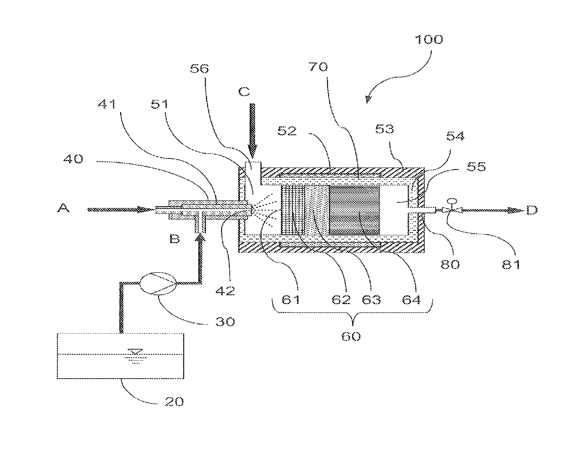
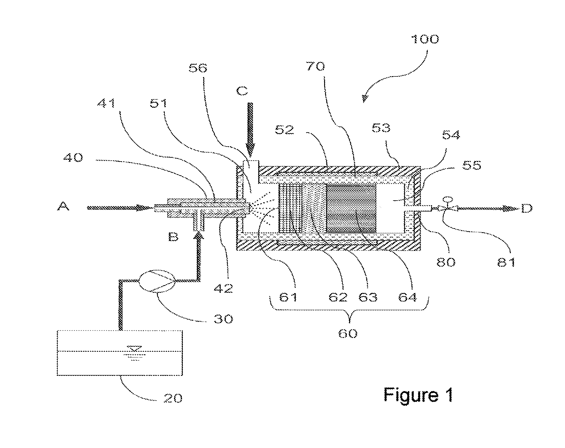
[0110]In practical example 2, the reactor is configured in such a way that the reactor is additionally heated in part as a result of counter flow heat exchange by the supplied hot carrier gas stream. In this context, the carrier gas stream is initially passed below the reactor head, via a double casing, counter to the flow direction in the inside of the double casing, to the reactor wall, and flows around said wall on the way to the reactor head. At the reactor head, the primary flow from the reactor double casing enters the reactor interior from the reactor double casing via a plurality of holes or alternatively via an annular gap in the region of the nozzle at the reactor head. In addition, an electrical resistance heater may be located in the double casing.

example 3

Practical Example 3

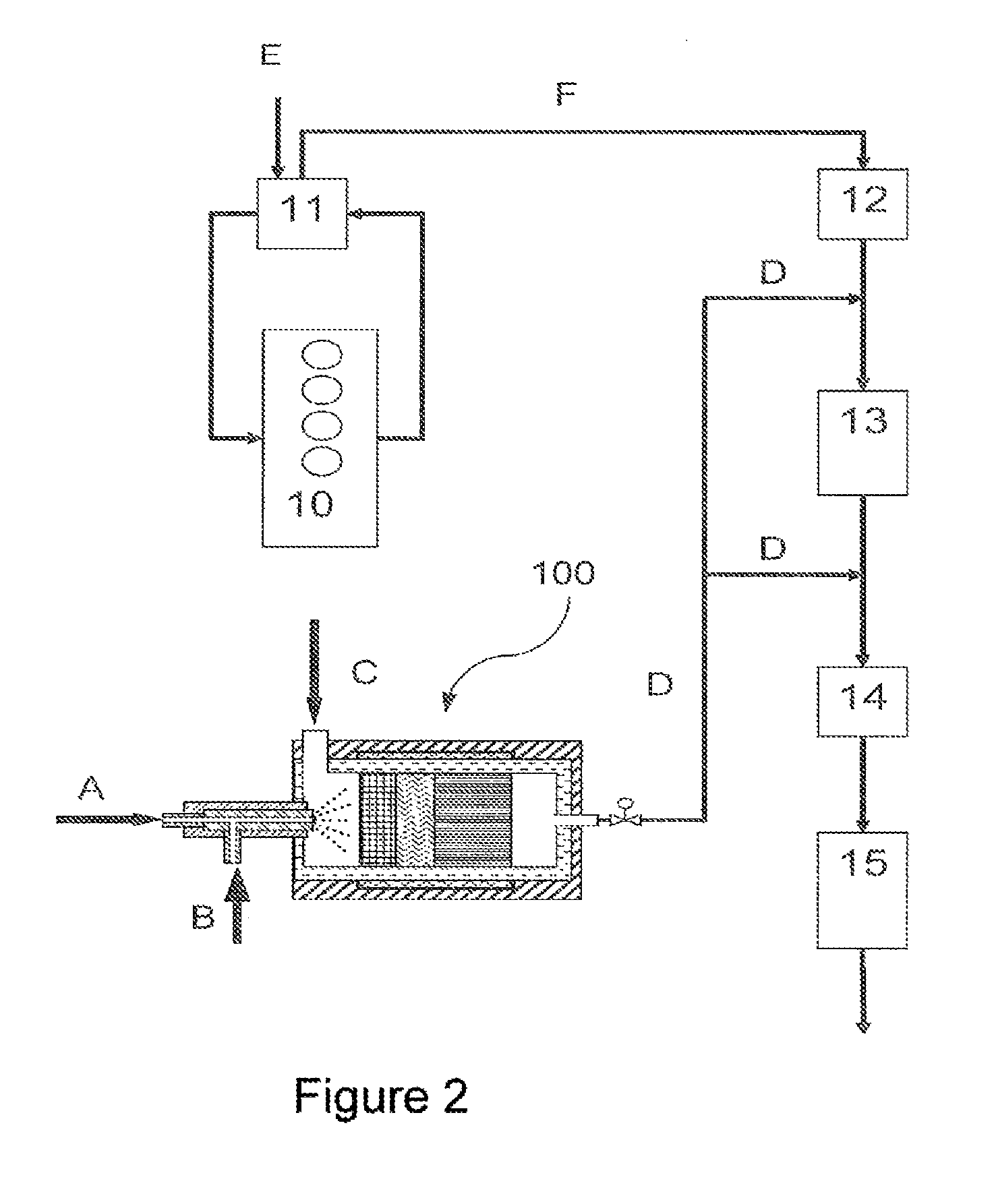
[0111]In practical example 3, the reactor is configured in such a way that the reactor is heated from the outside by heat exchange with hot components of a combustion engine or of a separate burner for exhaust heating or by hot gas flows, rather than by means of an electrical resistance heater. In this context, the heat can also be transported to the reactor via a heating tube over some distance.

example 4

Practical Example 4

[0112]In practical example 4, the reactor is configured in such a way that heat is supplied directly in the interior of the reactor by means of an electrically heatable Emikat catalyst from Emitec, instead of the reactor being heated from the outside. Alternatively heat can be generated in the reactor by glow plugs, model Champion (60 W, 11 V).


PUM

PropertyMeasurementUnit
Lengthaaaaaaaaaa
Angleaaaaaaaaaa
Angleaaaaaaaaaa

Abstract

The present invention relates to an ammonia gas generator for generating ammonia from an ammonia precursor substance and to the use thereof for reducing nitrogen oxides in exhaust, in particular from industrial facilities, from combustion engines, from gas engines, from diesel engines or from petrol engines.

Description

CROSS-REFERENCE TO RELATED APPLICATIONS[0001]This application is a National Phase application of International Application No. PCT / EP2012 / 062757, filed Jun. 29, 2012, which claims priority to German Patent Application No. 10 2011 106 233.9, filed Jul. 1, 2011, German Patent Application No. 10 2011 106 237.1, filed Jul. 1, 2011, and German Patent Application No. 10 2011 106 243.6, filed Jul. 1, 2011, each of which is incorporated herein by reference in its entirety.FIELD OF THE INVENTION[0002]The present invention relates to an ammonia gas generator for generating ammonia from an ammonia precursor substance and to the use thereof in exhaust treatment systems for reducing nitrogen oxides in exhaust.BACKGROUND[0003]The exhaust of internal combustion engines often contains substances of which the release into the environment is undesirable. Therefore, many countries set limits which have to be adhered to on the release of these pollutants, such as in the exhausts of industrial facilitie...

Claims


Application Information

Patent Timeline
IPC IPC(8): F01N3/00B01D53/56B01D53/90B01D53/92B01D53/94B01J8/04C01C1/04C01C1/08F01N3/20
CPCC01C1/08C01C1/086F01N3/2066F01N2240/25F01N2610/02F01N2610/10B01D53/90B01D53/9409B01D2251/2067B01D2251/21B01D2255/808B01D2255/902B01D53/94B01J8/0496Y02P20/52Y02T10/12B01D53/92B01D53/565B01D53/9431C01C1/04
Inventor GERHART, CHRISTIANSATTELMAYER, THOMASTOSHEV, PLAMEN
Owner ALZCHEM TROSTBERG
Features
  • R&D
  • Intellectual Property
  • Life Sciences
  • Materials
  • Tech Scout
  • Unparalleled Data Quality
  • Higher Quality Content
  • 60% Fewer Hallucinations
Learn More