Method for generating image for PET attenuation correction from MR image and computer program

a technology of generating an image and a computer program, which is applied in the direction of image enhancement, measurement using nmr, instruments, etc., can solve the problems of difficult to determine in which organ the tumor is located, the quantitative performance is greatly disturbed in deep parts of the subject, and the inability to directly obtain the radiation attenuation rate of the respective tissues

Active Publication Date: 2016-05-17
SHIMADZU CORP
View PDF22 Cites 1 Cited by
  • Summary
  • Abstract
  • Description
  • Claims
  • Application Information

AI Technical Summary

Benefits of technology

[0028]According to the present invention, in a region in which differences in the radiation attenuation correction value (also referred to as μ value) can be distinguished by referring to the pixel values of the MR image, μ values inherent to the tissues are substituted by the segmentation method. In a region in which a distinction cannot be made by using the pixel values of the MR image (for example, a low intensity region including bone and air), μ values are determined by referring to the standard image by the standard image reference method. Accurate μ values can thus be assigned to the region in which a distinction cannot be made by using the pixel values of the MR image, while individual differences and an affected area such as a brain defect portion can be accommodated.

Problems solved by technology

It may therefore be difficult to determine in which organ the tumor is.
As a result, quantitative performance is greatly disturbed in deep portions of the subject.
MRI collects intensities obtained from protons (hydrogen nuclei) in tissues, and therefore cannot directly obtain the radiation attenuation rate of the respective tissues.

Method used


Image

  • Method for generating image for PET attenuation correction from MR image and computer program
  • Method for generating image for PET attenuation correction from MR image and computer program
  • Method for generating image for PET attenuation correction from MR image and computer program

Examples


first embodiment

[0054]the present invention is implemented by a procedure shown in FIG. 4.

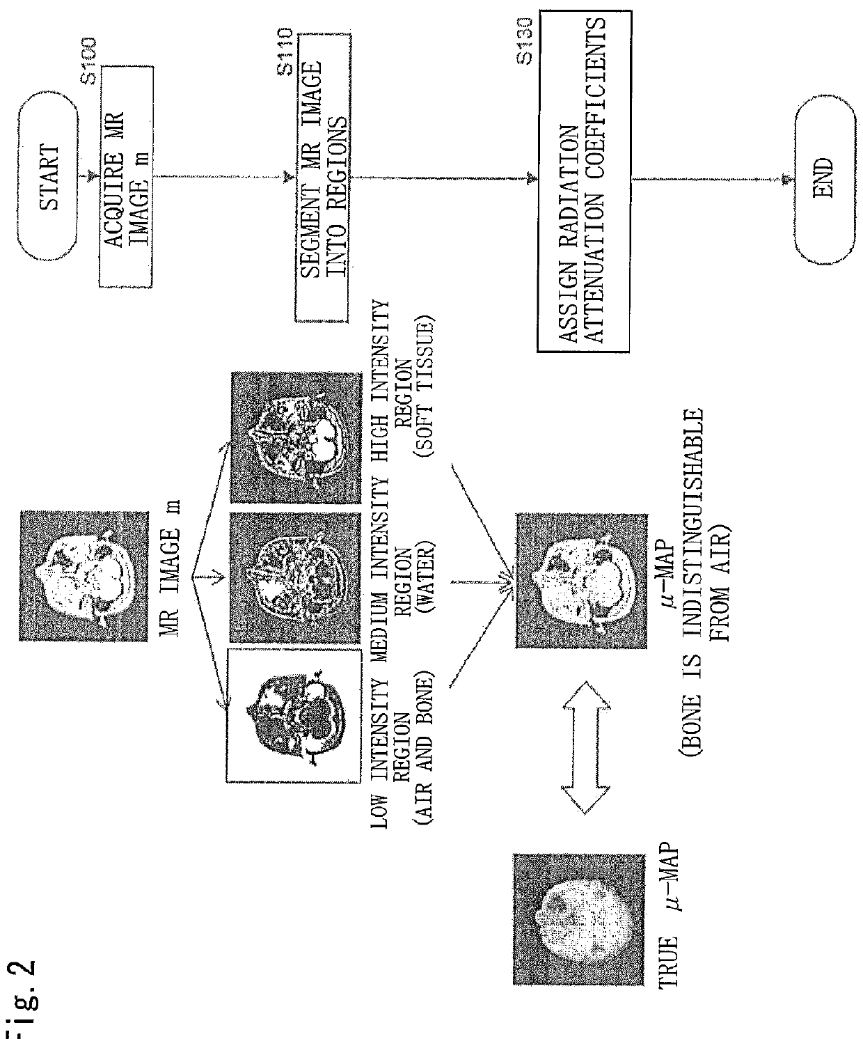
[0055]Specifically, in step S100, an MR image m is initially acquired as with the conventional segmentation method.

[0056]Next, in step S110, as illustrated in FIG. 5, the MR image is divided into, for example, high intensity regions corresponding to soft tissue, medium intensity regions corresponding to water, and low intensity regions corresponding to air and bone on the basis of the pixel values of the MR image.

[0057]Next, in step S120, whether each intensity region includes multiple tissues having different radiation attenuation coefficients is determined. If the determination result is negative and the intensity region is determined to be a high intensity region corresponding to soft tissue or a medium intensity region corresponding to water, the radiation attenuation coefficient of soft tissue (for example, μ=0.095) is assigned to the high intensity region, and the radiation attenuation coefficient of wat...

fourth embodiment

[0066]Next, FIG. 8 shows the present invention in which a difference in resolution is absorbed by a different method.

second embodiment

[0067]In the present embodiment, in similar processing to that of the second embodiment shown in FIG. 6, if the determination result of step S120 is positive, the low intensity region is expanded in step S290. Then, in step S300, the pixel values of the morphologically transformed standard radiation attenuation image are assigned.

[0068]According to the present embodiment, a drop in the radiation attenuation coefficients near bone regions can be suppressed to connect the radiation attenuation image and the MR image more smoothly.


PUM


Abstract

When an image for PET attenuation correction is generated from an MR image, the MR image captured by MRI is segmented into regions according to pixel values. In a region in which a radiation attenuation coefficient is considered to be uniform, a radiation attenuation correction value is determined by referring to an existing radiation attenuation correction value table. In a region including multiple tissues having different radiation attenuation coefficients, a radiation attenuation correction value is determined by referring to a standard image. In such a manner, an image for PET attenuation correction in which tissues having similar pixel values in the MR image but different attenuation coefficients for radiation can be distinguished and that can accommodate individual differences and an affected area such as a space occupying lesion (for example, a cancer, abscess, or the like) and an organic defect is generated.

Description

TECHNICAL FIELD[0001]The present invention relates to a method for generating an image for PET attenuation correction from an MR image and a computer program, and more particularly to a method for generating an image for PET attenuation correction from an MR image by which a high-precision image for PET attenuation correction can be generated when generating an image for PET attenuation correction from an MR image, and a computer program for executing this method.BACKGROUND ART[0002]Inspection devices capable of observing inside the human body in a minimally invasive manner, such as X-ray CT (computed tomography) and MRI (magnetic resonance imaging), have become widely available in recent years and been contributing significantly to medical diagnosis. Such apparatuses mainly provide a morphological image obtained by visualizing a tissue structure of the living subject as a tomographic image or volume data. In contrast, nuclear medical imaging, typified by PET (positron emission tomo...

Claims


Application Information

Patent Timeline
Patent Type & Authority Patents(United States)
IPC IPC(8): G06K9/00G01T1/16A61B6/03G01R33/48A61B5/00G06T7/00G06T11/00A61B5/055
CPCG01T1/1603A61B5/055A61B5/0035A61B6/037G06T11/005G01R33/481G06T7/0081A61B2576/026G06T2207/10088G06T2207/10104G06T2207/30004G06T7/11G16H30/40G06T2211/464
Inventor YAMAYA, TAIGAOBATA, TAKAYUKISUGA, MIKIOKAWAGUCHIYAMAKAWA, YOSHIYUKI
Owner SHIMADZU CORP
Why Eureka
Try Eureka