Catadioptric optical system with multi-reflection element for high numerical aperture imaging
a catadioptric optical system and optical element technology, applied in the field of optical imaging, can solve the problems of limited numerical aperture, high obscuration ratio, and large total length of the optical system used in the direction of incident light,
- Summary
- Abstract
- Description
- Claims
- Application Information
AI Technical Summary
Benefits of technology
Problems solved by technology
Method used
Image
Examples
numerical examples
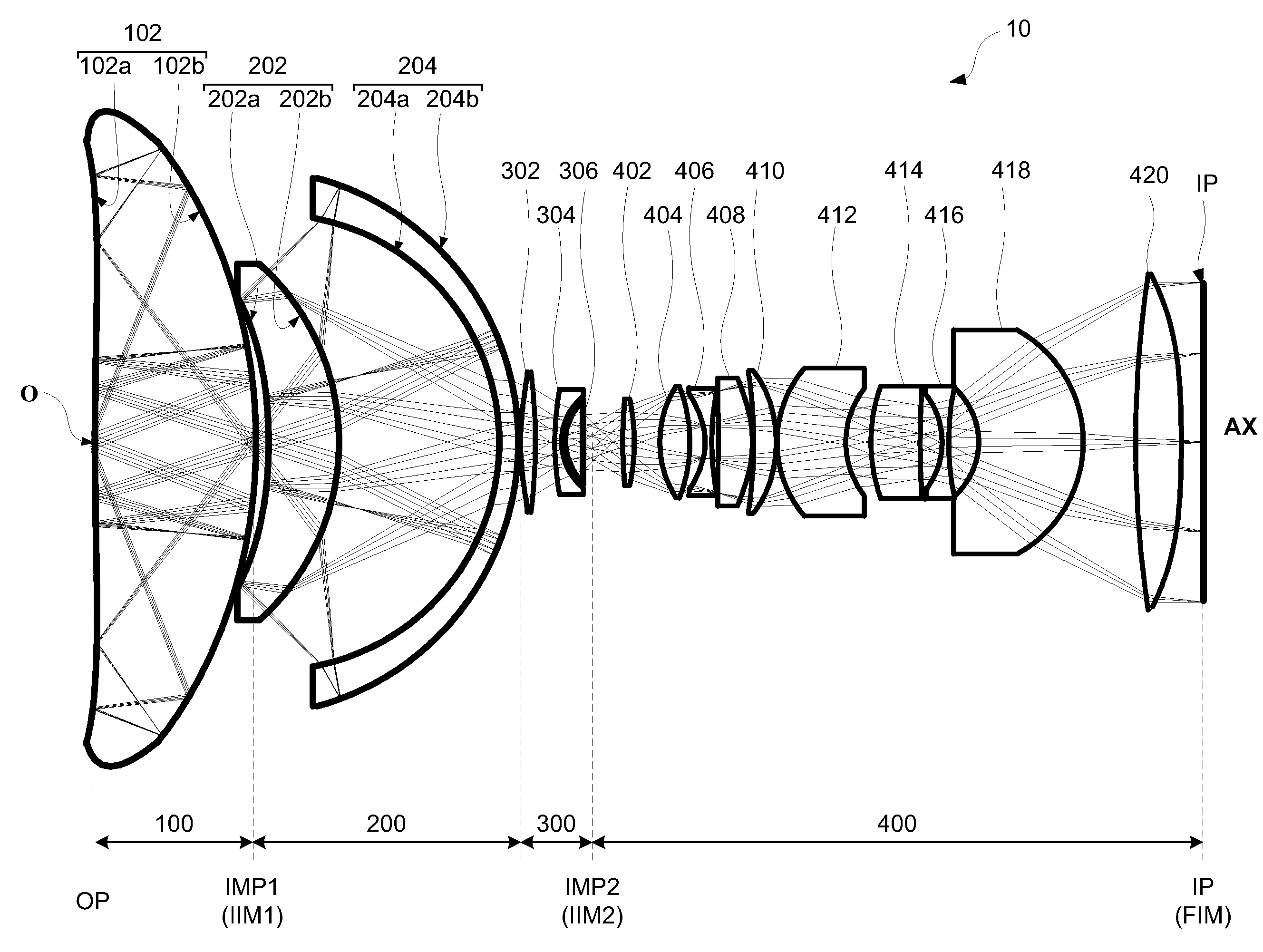
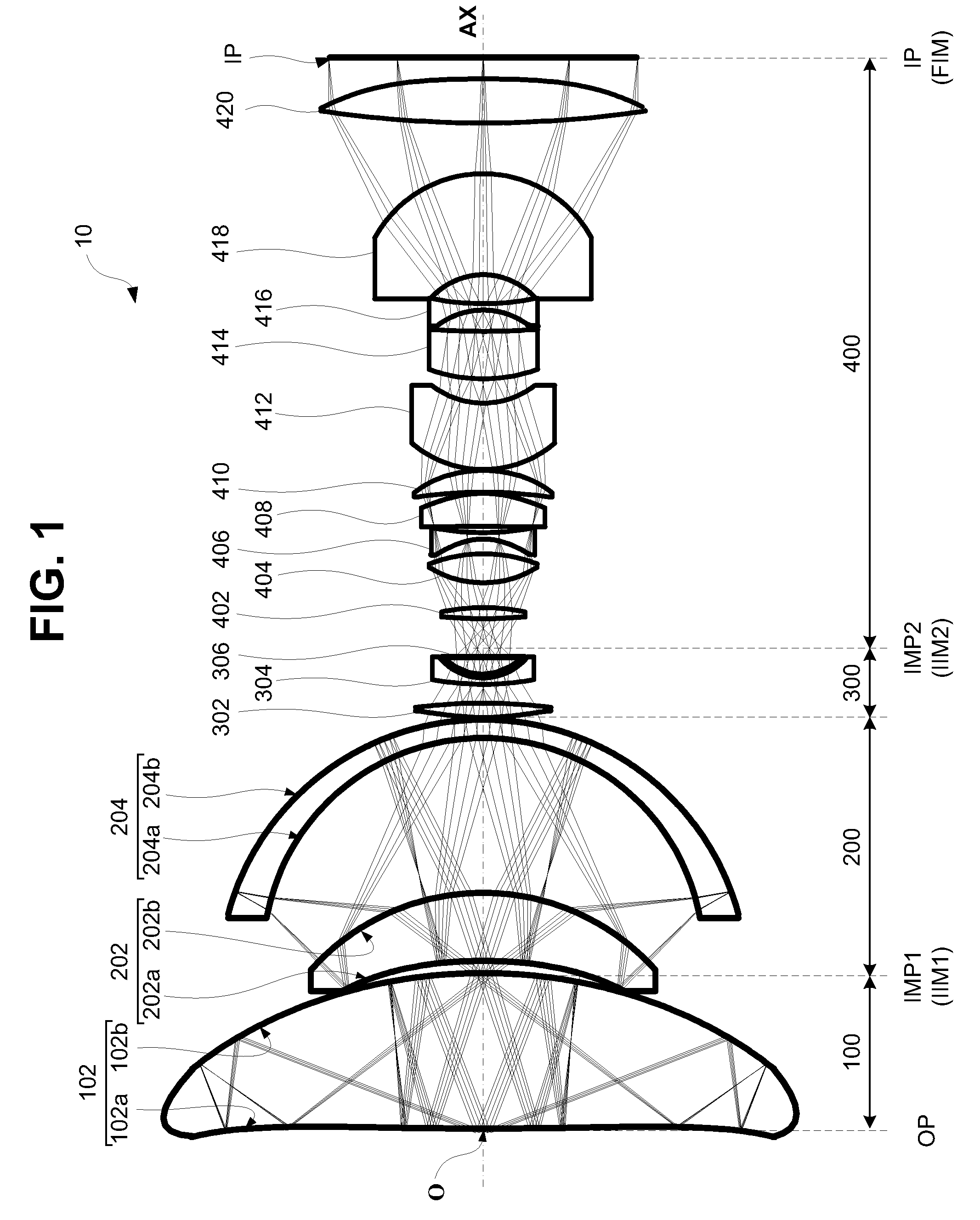
[0134]Data corresponding to the following numerical examples 1 and 2 are representative of the catadioptric optical system 10 illustrated in FIG. 1 and the catadioptric optical system 20 illustrated in FIG. 6. In the numerical examples presented herein, the reference indicia “i” (where i=1, 2, 3 . . . ) denotes the order of surfaces in the optical system from the object plane OP to the image plane IP. With this premise, the “Radius” data Ri corresponds to an ith radius of curvature (at the ith plane); thickness Ti denotes an on-axis distance (or space) between the ith and (i+1)th surface; the reference ndi and νdi respectively denote the index of refraction and Abbe number of the material of the ith optical element with respect to the Fraunhoffer d-line. A surface number without data for ndi and νdi indicates that this surface number represents an air space. A radius R=1.00E+18 (where 1E+X is equivalent to 1×10+X) denotes a substantially infinite radius, i.e., a flat surface. In add...
numerical example 1
[0137]Data corresponding to numerical example 1 represents a catadioptric optical system comprising, in order from an object side to an image side, a first catadioptric group, a second catadioptric group and a field lens group and a dioptric group disposed in axial alignment with each other, as illustrated in FIG. 1. In the catadioptric optical system of Numerical Example 1, the first catadioptric group is configured to form, at a first intermediate image plane, a first intermediate image of an object disposed at an object plane; and the second catadioptric group and the field lens group are configured to together form, at a second intermediate image plane, a second intermediate image based on the first intermediate image. A dioptric group is configured to magnify the second intermediate image and to form, at an image plane, a final image of the object based on the second intermediate image.
[0138]
TABLE 3Optical element data for Numerical Example 1SurfaceRTndνd 11.00E+181.9891.77349....
numerical example 2
[0140]Data corresponding to numerical example 2 represents a catadioptric optical system comprising, in order from an object side to an image side, a first catadioptric group, a second catadioptric group, and a field lens group disposed in axial alignment with each other, as illustrated in FIG. 6. The first catadioptric group is configured to form, at a first intermediate image plane, a first intermediate image of an object disposed at an object plane. And the second catadioptric group and the lens group are configured to together form, at an image plane, a final image of the object based on the first intermediate image.
[0141]
TABLE 5Optical element data for Numerical Example 2SurfaceRTndνd 11.00E+180.2501.77349.57 2*294.78114.9991.77349.57 3*−105.885−14.9991.77349.57 4*294.78114.9991.77349.57 5*−105.885−14.9991.77349.57 6*294.78114.9991.77349.57 7*−105.885−14.9991.77349.57 8*294.78114.9991.77349.57 9*−105.8851.5631.77349.5710*−19.50936.6081.77349.5711*−41.203−36.6081.77349.5712*−19....
PUM
 Abstract
Description
Claims
Application Information
 - R&D
- Intellectual Property
- Life Sciences
- Materials
- Tech Scout
- Unparalleled Data Quality
- Higher Quality Content
- 60% Fewer Hallucinations
Browse by: Latest US Patents, China's latest patents, Technical Efficacy Thesaurus, Application Domain, Technology Topic, Popular Technical Reports.
© 2025 PatSnap. All rights reserved.Legal|Privacy policy|Modern Slavery Act Transparency Statement|Sitemap|About US| Contact US: help@patsnap.com


