
Catadioptric system and image pickup apparatus equipped with same

a catadioptric system and image pickup technology, applied in the field of catadioptric system and image pickup apparatus equipped with same, can solve the problems of insufficient size of imaging area

Inactive Publication Date: 2013-03-14
CANON KK
View PDF4 Cites 2 Cited by
  • Summary
  • Abstract
  • Description
  • Claims
  • Application Information

AI Technical Summary

Benefits of technology

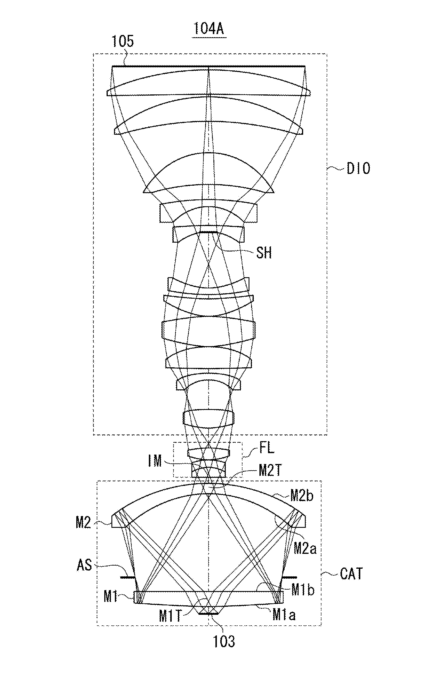
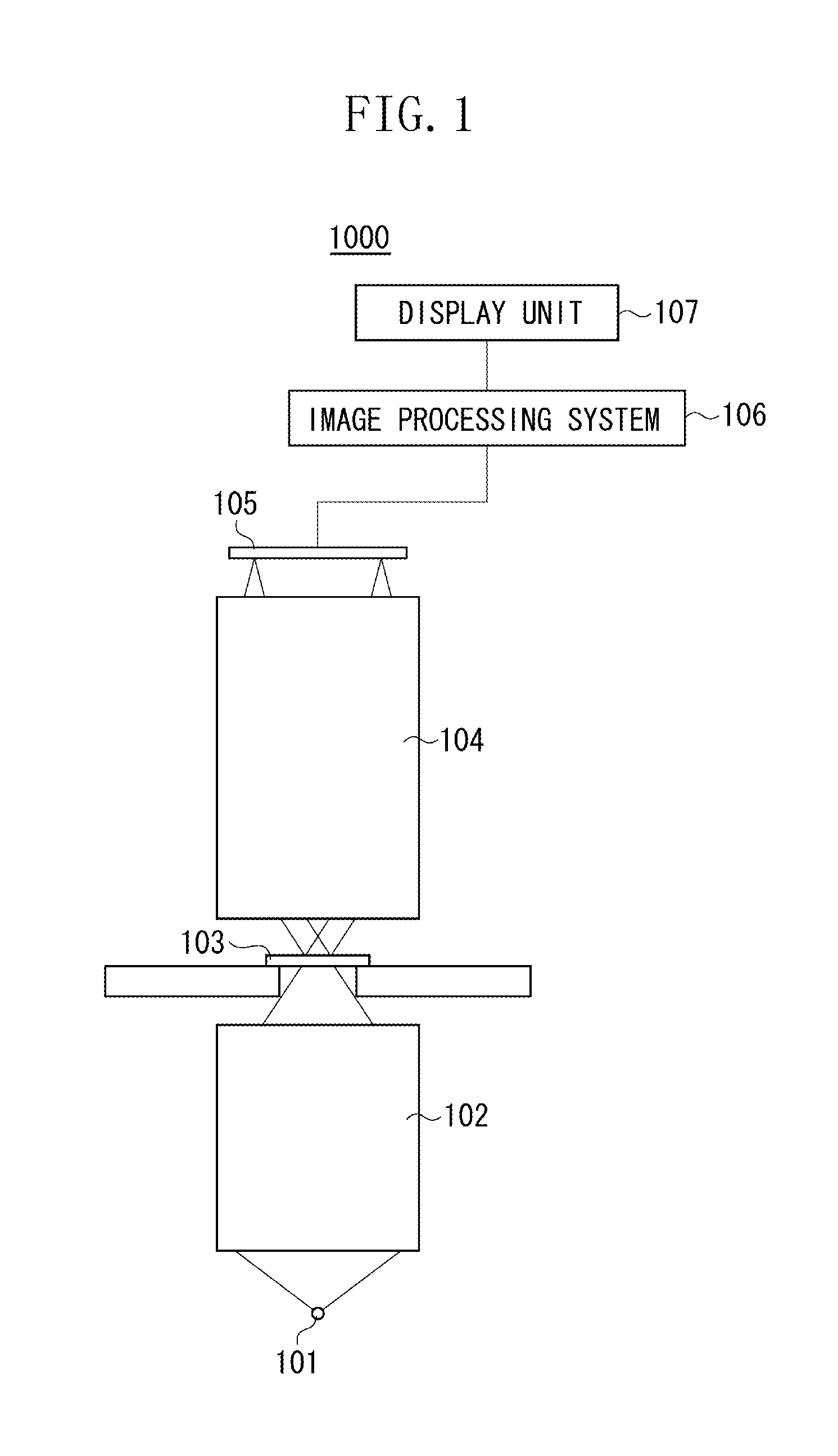
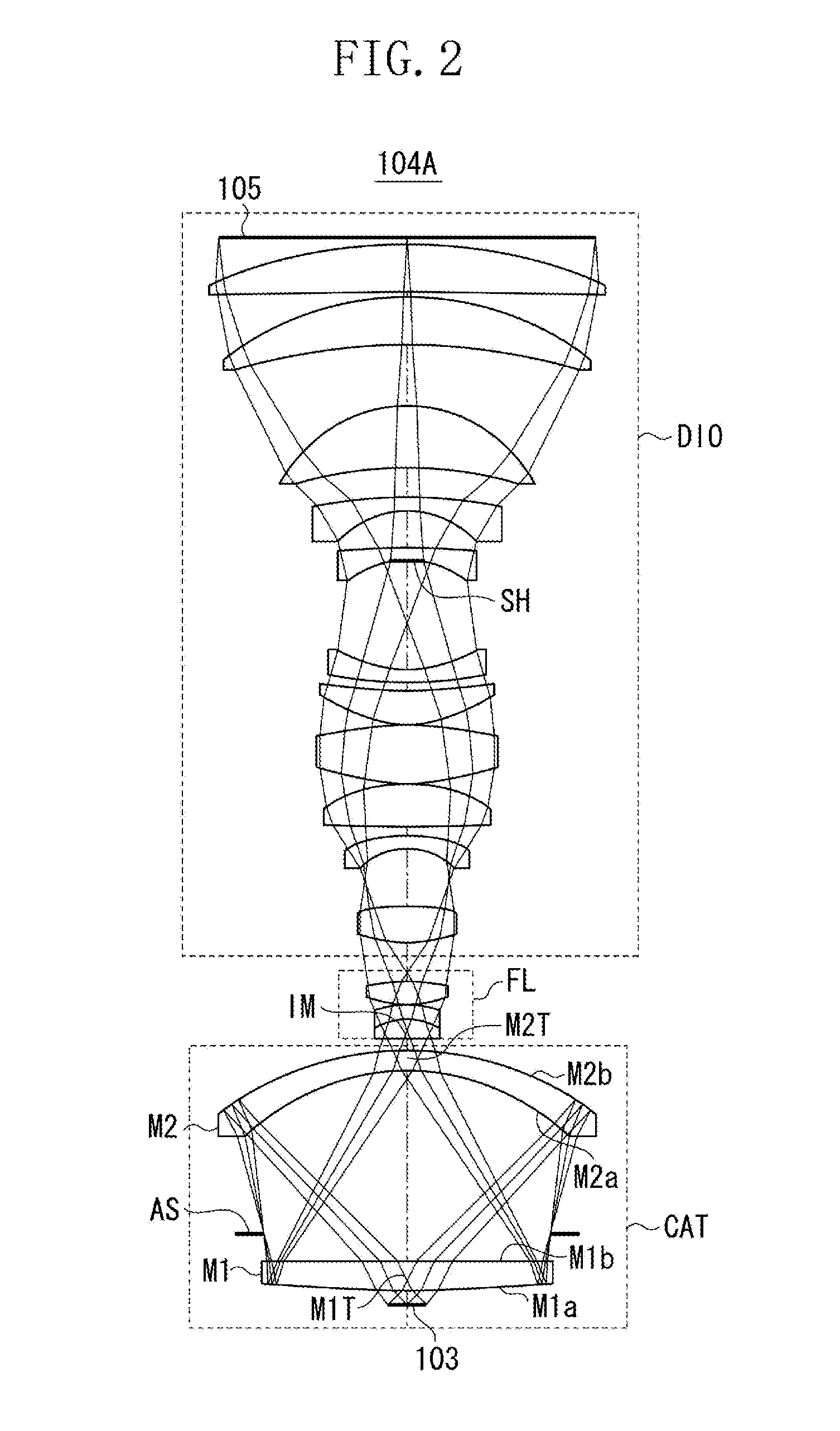
The present invention is about a catadioptric system used in optical instruments. The system includes a catadioptric unit, a field lens unit, and a dioptric unit. The catadioptric unit has three optical elements, which include two transmissive units and a reflective surface. The light from the object sequentially passes through the first and second transmissive units, and then through the second reflective surface before reaching the field lens unit. The patent text has provided some values for the refractive index, radii of curvature, and thickness of the optical elements. The technical effect of this patent is to provide a better understanding of the optical properties of the catadioptric system and to improve the performance of the system in optical instruments.

Problems solved by technology

Therefore, as the size of a pathologic sample is increased, the number of imaging operations is increased, and thus, there is a problem in that much time is taken to acquire the image data of the entire pathologic sample.
However, in the optical system discussed in Japanese Patent Publication No. 60-034737, although various aberrations are effectively reduced over the entire visible light range, the size of an imaging area is not necessarily sufficient.
In addition, in the optical system discussed in Japanese Patent Application Laid-Open (Translation of PCT Application) No. 2007-514179, although various aberrations are effectively reduced over the entire visible light range with high resolving power, the size of an imaging area is not necessarily sufficient.
In addition, although the optical system discussed in WO00 / 39623 has high resolving power over a wide range, the wavelength range in which various aberrations are effectively corrected does not cover the entire visible light range and is thus not adequate for visible-light microcopy.

Method used


Image

  • Catadioptric system and image pickup apparatus equipped with same
  • Catadioptric system and image pickup apparatus equipped with same
  • Catadioptric system and image pickup apparatus equipped with same

Examples


numerical example 1

[0058]

Rapl = 87.52 RM2a = −87.05νM2 = 40.75SurfaceNumberrdNdνdObject5.31Plane 1572.9611.741.5264.14 2−3971.9370.93 3−87.057.371.5840.75 4−115.96−7.371.5840.75 5−87.05−60.93 6Aperture −10.00Stop 7−3971.93−11.741.5264.14 8572.9611.741.5264.14 9−3971.9370.9310−87.057.371.5840.7511−115.964.4012−280.627.551.7345.7513−24.255.001.7627.5814−63.130.501544.308.031.6260.3216−134.0415.131764.2914.171.5658.8018−57.90 20.9319−26.525.001.7033.9420−60.243.37212035.3815.681.6335.4622−70.44 0.8923117.93 21.531.6839.5824−74.17 0.502556.7912.021.7430.9726177.00 3.0627165.395.001.7627.582853.4240.6729−38.60 5.001.7627.5830−229.8513.9931−35.70 5.001.7627.5832−181.7911.2233−143.3022.661.5253.6434−56.43 23.5735−219.0417.881.7534.2436−110.371.0937−4269.6117.811.6357.6938−282.703.00ImagePlaneAspheric CoefficientSurfaceNumberkabcdefg1, 8 0.00E+00  2.87E−08−2.21E−12  1.43E−15−3.23E−19  6.13E−23−7.84E−275.67E−314, 110.00E+00  1.38E−08  1.43E−12  1.18E−16  9.15E−21  1.75E−24−1.32E−282.36E−32150.00E+00−2.86E−06−1...

numerical example 2

[0059]

Rapl = 147.19RM2a = −118.31νM2 = 70.24SurfaceNumberrdNdνdObject13.39Plane 1736.6124.081.4970.24 2−9661.7597.67 3−118.319.381.4970.24 4−170.29−9.381.4970.24 5−118.31−97.67 6−9661.75−24.081.4970.24 7736.6124.081.4970.24 8−9661.7597.67 9−118.319.381.4970.2410−170.2910.0011−458.415.891.6458.3712−119.833.2913−54.795.001.6533.7914−998.8211.551.6260.2515−54.520.731679.777.041.6260.2917483.7434.051859.0211.531.7640.1019109.310.502065.7020.521.4970.3521−118.8126.0022Aperture18.84Stop23−49.2633.311.8125.4324−79.270.5025122.5326.671.6455.3826−86.460.502757.9015.511.4970.352878.6717.3929−124.445.741.5742.863058.4915.6431−147.568.961.7647.8232−75.8111.9033−59.728.101.6038.0334272.559.1235−178.6219.271.7234.7236−68.400.50371362.8916.901.5160.4938−142.7710.50ImagePlaneAspheric CoefficientSurfaceNumberkabcdefg1, 7 0.00E+00  6.72E−09  6.14E−14  2.27E−17−9.74E−22  1.18E−25−5.31E−302.75E−344, 100.00E+00  5.58E−09  2.43E−13  9.28E−1B  1.61E−22  2.65E−26−9.34E−315.28E−35170.00E+00  6.69E−07−6.19E−...

numerical example 3

[0060]

Rapl = 142.21RM2a = −167.82νM2 = 52.43SurfaceNumberrdNdνdObject13.72Plane 1770.3922.331.5258.90 22378.98111.82 3−167.8211.371.5252.43 4−207.81−11.371.5252.43 5−167.82−111.82 62378.98−22.331.5258.90 7770.3922.331.5258.90 82378.98111.82 9−167.8211.371.5252.4310−207.815.3211−93.8616.271.7444.8512−69.678.3113−61.439.191.7627.5814144.619.271.6357.8515−53.510.501647.7114.721.6260.3217140.4011.601857.1321.311.7048.3119−40.246.481.6732.0720−89.7116.8621Aperture13.99Stop22−32.965.711.5160.7423−270.018.9724−379.4914.341.7528.1525−67.231.2426211.5519.561.5857.8127−76.670.522859.1117.641.6260.34291974.656.9930−254.085.061.7627.583166.6517.1432−70.168.911.7437.4633−47.204.8234−41.795.001.5163.5535327.6920.1236−38.886.831.7627.5837−156.164.6038−158.3122.611.7442.7039−61.080.7640353.1519.111.6949.2741−226.3917.00ImagePlaneAspheric CoefficientSurfaceNumberkabcdefg1, 7 0.00E+00  3.34E−09−6.39E−14  1.16E−17−6.40E−22  3.18E−26−8.25E−311.39E−354, 100.00E+00  2.84E−09  8.32E−14  2.31E−18  5.53E−18...


PUM


Abstract

A catadioptric unit includes, in order from an object side to an image side, a first optical element including a first transmissive unit having positive refractive power disposed in the vicinity of an optical axis and, on the object side thereof, a first reflective unit disposed at an outer circumference relative to the first transmissive unit and having a reflective surface; and a second optical element including a second transmissive unit having negative refractive power in the vicinity of the optical axis and, on the image side thereof, a second reflective unit disposed at an outer circumference relative to the second transmissive unit and having a reflective surface. Radii of curvature of object-side and image-side surfaces of the second optical element, a thickness along the optical axis and a refractive index of a material of the second optical element are set to satisfy predetermined conditions.

Description

BACKGROUND OF THE INVENTION[0001]1. Field of the Invention[0002]The present invention relates to a catadioptric system which is appropriate for magnification and observation of an object and an image pickup apparatus equipped with the catadioptric system.[0003]2. Description of the Related Art[0004]In the related art, in pathologic examination, pathologic samples are directly observed with eyes by using an optical microscope. Recently, a virtual microscope for acquiring image data of pathologic samples to be observed on a display has been used. Since the image data of the pathologic sample can be observed on a display by using the virtual microscope, a plurality of persons can simultaneously observe the sample. In addition, if the virtual microscope is used, there are many advantages, for example, in that the image data can be shared with pathologists at remote sites.[0005]However, in the case where the microscope has a small imaging area, a pathologic sample needs to be divided int...

Claims


Application Information

Patent Timeline
Patent Type & Authority Applications(United States)
IPC IPC(8): G02B17/08H04N5/232
CPCG02B17/08G02B13/18G02B13/22G02B17/0808G02B17/0856G02B17/0888G02B21/04
Inventor KAJIYAMA, KAZUHIKOSUZUKI, MASAYUKIKATASHIBA, YUJI
Owner CANON KK
Learn More