Electrically driven turbocharger device

a turbocharger and electric motor technology, applied in the direction of positive displacement liquid engines, pumps, machines/engines, etc., can solve the problems of increased loss, reduced flow rate of air inhaled by the compressor as well as delivered by the compressor, and expected performance, so as to prevent compressor deterioration and damage, the effect of preventing compressor deterioration and preventing deterioration of compressor strength

Active Publication Date: 2016-05-03
MITSUBISHI HEAVY IND ENGINE & TURBOCHARGER LTD
View PDF17 Cites 0 Cited by
  • Summary
  • Abstract
  • Description
  • Claims
  • Application Information

AI Technical Summary

Benefits of technology

[0022]In view of the difficulties in the conventional technology, the present invention aims at providing an electrically driven turbocharger device which is provided with a cooling device to cool the electric motor or the inverter by use of the intake air delivered by the compressor, wherein the decrease in the flow rate capacity and the performance of the compressor can be constrained, the decrease being attributable to the loss of the intake air flow such as the pressure loss; and the compressor can be prevented from being overheated, and the decrease of the strength or the breakage due to the deterioration can be prevented.Means to Solve the Subjects
[0082]With the configuration as described above, the compressor delivery air flow rate can be secured, and the compressor performance deterioration can be prevented. Further, since the low temperature outside air can be induced from the outside air induction pipe toward the compressor, the temperature increase of the compressor delivery air can be constrained and the compressor strength deterioration and damage can be prevented.

Problems solved by technology

However, if the intake air flow passage is made narrow, the pressure loss is increased so that the flow rate of the air inhaled by the compressor as well as delivered by the compressor is decreased.
Accordingly, there arises a problem that the expected performance and the efficiency of the compressor may be deteriorated.
Consequently, the compressor wheel is overheated and there may be an apprehension that the strength of the compressor wheel is decreased.
In addition, the compressor wheel is usually made from, for instance, aluminum, and the decreased strength may cause the breakage of the compressor wheel under the centrifugal forces acting on the compressor wheel.

Method used


Image

  • Electrically driven turbocharger device
  • Electrically driven turbocharger device
  • Electrically driven turbocharger device

Examples


Embodiment Construction

[0092]Hereafter, the present invention will be described in detail with reference to the modes or embodiments shown in the figures. However, the dimensions, materials, shape, the relative placement and so on of a component described in these modes or embodiments shall not be construed as limiting the scope of the invention thereto, unless especially specific mention is made.

First Mode

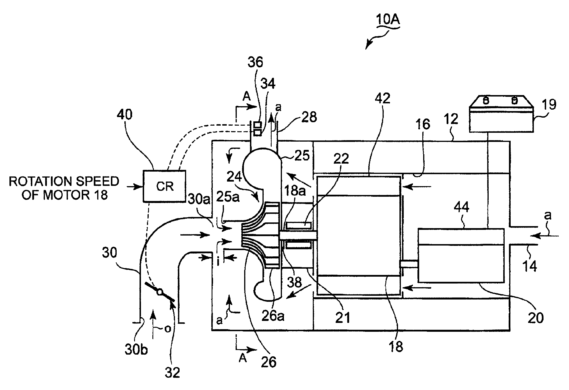
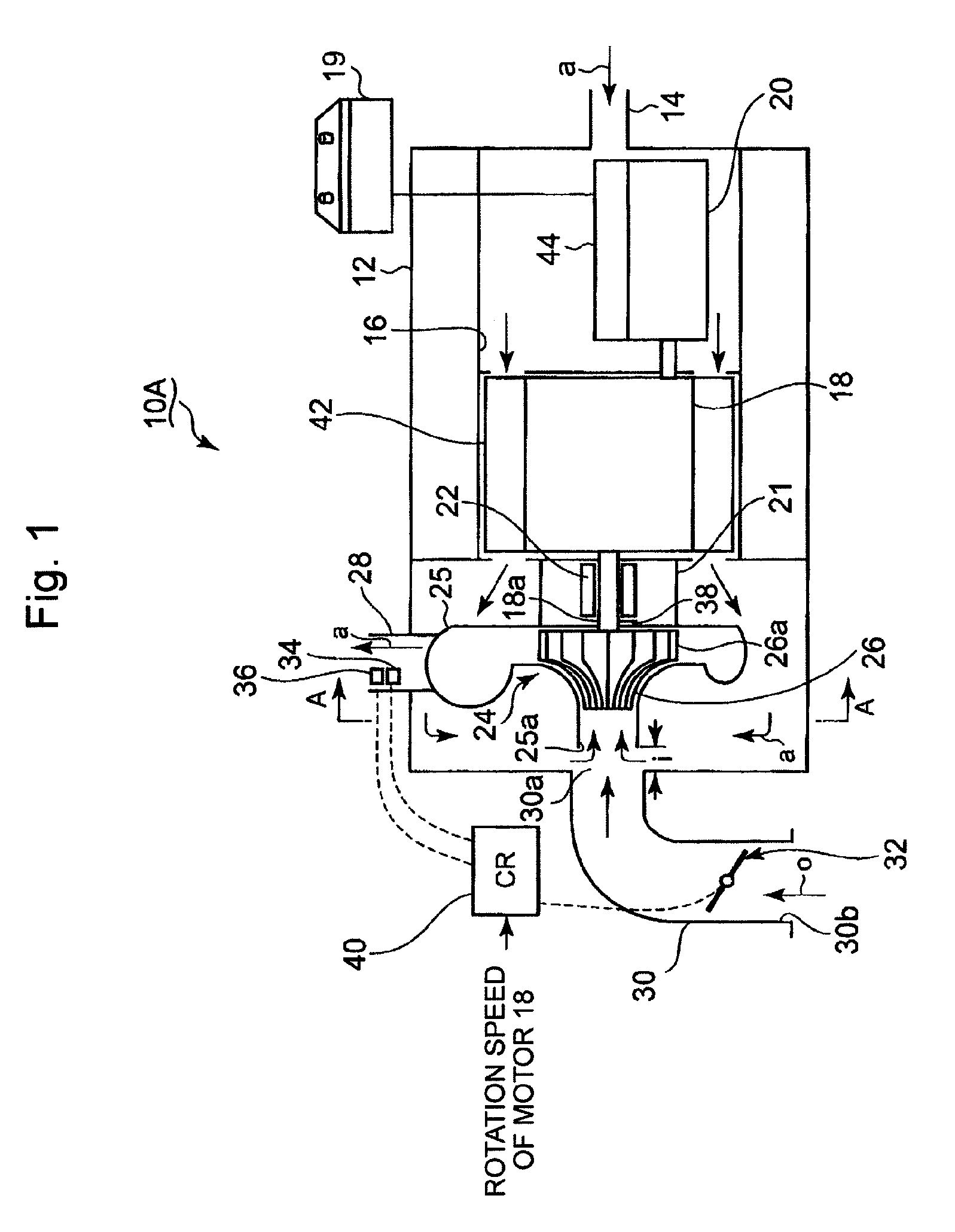
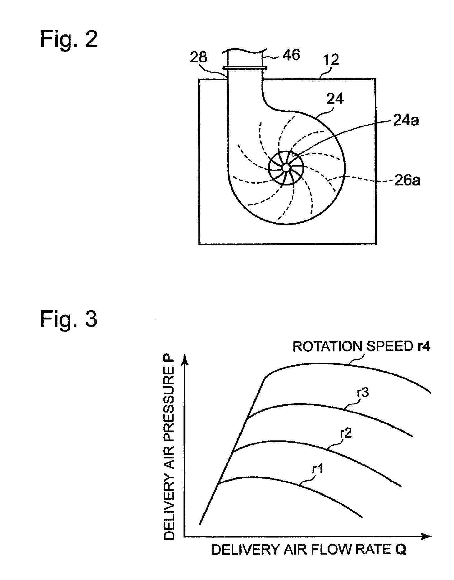
[0093]Based on FIGS. 1 to 3, an electrically driven turbocharger device 10A according to the first mode of the present invention is now explained. FIGS. 1 and 2 show the electrically driven turbocharger device 10A which is provided at the intake air flow passage of an engine (not shown) mounted on a vehicle such as an automobile. In FIGS. 1 and 2, an intake air pipe 14 is connected to a side surface of a gas-tight housing 12 of a quadrangle box shape; an intake air flow passage 16 is formed in the gas-tight housing 12. In the intake air flow passage 16, an electric motor rotating the compressor is arran...


PUM


Abstract

Inside of a gas-tight housing, an electric motor, an inverter and a compressor are housed. Further, an intake air pipe is connected to the gas-tight housing. Inside of the gas-tight housing, an intake air flow passage is formed. Further, a connection opening of an outside air induction pipe provided with a flow rate regulating valve is arranged so as to face a suction opening of a compressor. When the delivery air flow rate as well as the delivery air pressure of the compressor is reduced due to the pressure loss and the like of the intake air ‘a’ which passes through the air flow passage and cools the electric motor and the inverter, an outside air ‘o’ of low temperature is induced so that: the capacity shortage as well as the performance deterioration of the compressor is constrained; and the over-heating of the compressor is constrained.

Description

BACKGROUND OF THE INVENTION[0001]1. Field of the Invention[0002]The present invention relates to an electrically driven turbocharger device installed into an internal combustion engine which is mounted on an automobile and the like, wherein the decreasing of the compressor capacity as well as the increase of the delivery air temperature can be constrained, while the inverter and the motor which are installed in the electrically driven turbocharger device can be cooled by the air inhaled into the electrically driven turbocharger device.[0003]2. Background of the Invention[0004]In the conventional internal combustion engine used for an automobile and the like, the engine is often combined with an exhaust gas turbocharger in which a turbine is driven at high speed by the exhaust gas emitted from the engine and the turbine drives a compressor via a common shaft which the turbine possesses with the compressor. Thus, in order to drive the turbocharger, the exhaust gas emitted from the int...

Claims


Application Information

Patent Timeline
Patent Type & Authority Patents(United States)
IPC IPC(8): F02B39/10F02B37/22F02B37/04F02B39/00F01P7/02
CPCF02B39/10F02B37/04F02B37/225F02B39/005F01P7/02Y02T10/144Y02T10/12F02B33/00F02B39/00
Inventor HAYASHI, NORIYUKIYAMASHITA, YUKIO
Owner MITSUBISHI HEAVY IND ENGINE & TURBOCHARGER LTD
Why Eureka
Try Eureka