
Multiple domain anomaly detection system and method using fusion rule and visualization

a multi-domain anomaly and detection system technology, applied in the field of domain specific and cross-domain analysis of information, can solve the problems of inflexible prone to false alarms, and prone to conventional anomaly detection system

Active Publication Date: 2016-04-26
ZHAO YING +2
View PDF7 Cites 27 Cited by
  • Summary
  • Abstract
  • Description
  • Claims
  • Application Information

AI Technical Summary

Benefits of technology

The system reduces false alarm rates by providing more accurate and dynamic critical event notifications through domain-independent analysis, leveraging multiple-domain anomaly scores and intuitive visualization interfaces.

Problems solved by technology

Conventional anomaly detection systems tend to generate many false alarm rates because they tend to be overly domain-dependent and / or lack coherent methods to analyze domain-specific anomalous data across multiple domains.
However, this critical event notification may simply be a false alarm in some instances, because the conventional anomaly detection system may fail to take data from other domains (i.e. domains outside of motorboat speed monitoring), such as the current weather conditions and a news event impacting in the same region into account for determining what should be considered an anomalous event worthy of a critical event notification.
Furthermore, the conventional anomaly detection systems tend to manually define what triggers a data set to be anomalous.
Therefore, the conventional anomaly detection system tends to be inflexible in taking dynamically-changing normal data profile into account for generating a critical event notification.
The manually-set trigger for anomalous data makes conventional anomaly detection systems to be prone to false alarms during critical event monitoring.

Method used


Image

  • Multiple domain anomaly detection system and method using fusion rule and visualization
  • Multiple domain anomaly detection system and method using fusion rule and visualization
  • Multiple domain anomaly detection system and method using fusion rule and visualization

Examples


Embodiment Construction

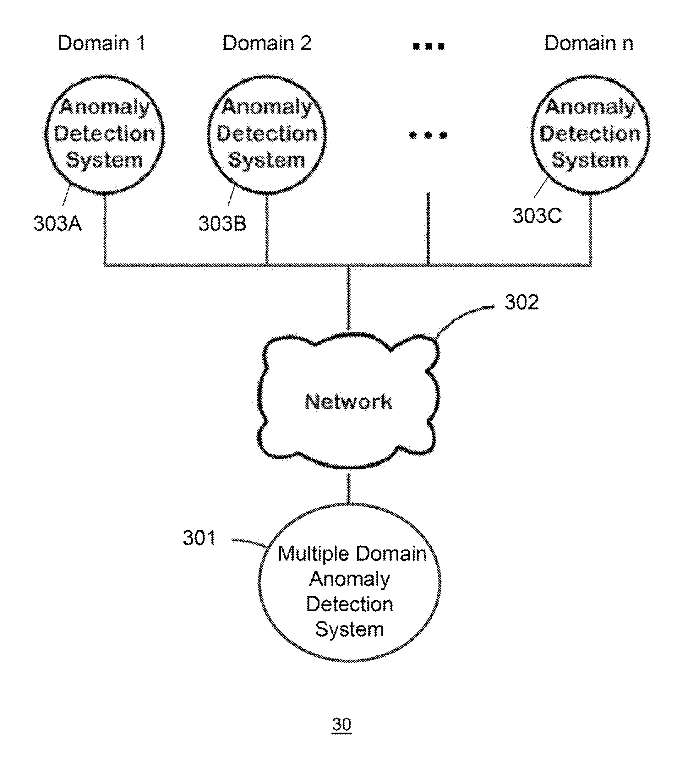
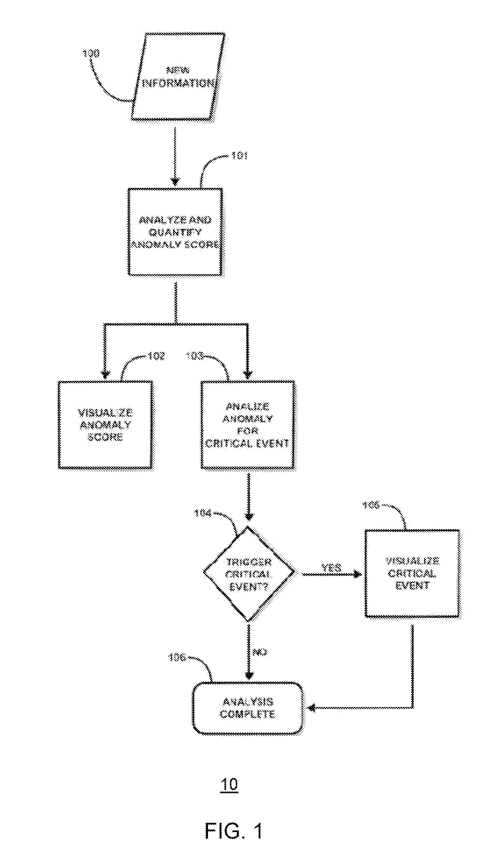
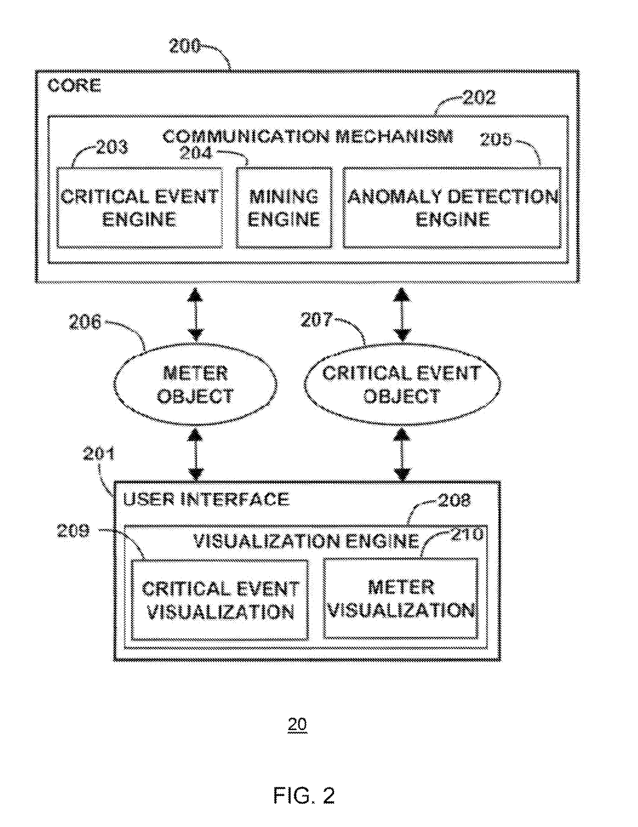
[0016]Specific embodiments of the invention will now be described in detail with reference to the accompanying figures. Like elements in the various figures are denoted by like reference numerals for consistency.

[0017]In the following detailed description of embodiments of the invention, numerous specific details are set forth in order to provide a more thorough understanding of the invention. However, it will be apparent to one of ordinary skill in the art that the invention may be practiced without these specific details. In other instances, well-known features have not been described in detail to avoid unnecessarily complicating the description.

[0018]The detailed description is presented largely in terms of description of shapes, configurations, and / or other symbolic representations that directly or indirectly resemble one or more apparatuses and methods for multiple domain anomaly detection systems using fusion rules and related visualizations. These descriptions and representat...


PUM


Abstract

The present invention discloses various embodiments of multiple domain anomaly detection systems and methods. In one embodiment of the invention, a multiple domain anomaly detection system uses a generic learning procedure per domain to create a “normal data profile” for each domain based on observation of data per domain, wherein the normal data profile for each domain can be used to determine and compute domain-specific anomaly data per domain. Then, domain-specific anomaly data per domain can be analyzed together in a cross-domain fusion data analysis using one or more fusion rules. The fusion rules may involve comparison of domain-specific anomaly data from multiple domains to derive a multiple-domain anomaly score meter for a particular cross-domain analysis task. The multiple domain anomaly detection system and its related method may also utilize domain-specific anomaly indicators of each domain to derive a cross-domain anomaly indicator using the fusion rules.

Description

BACKGROUND OF THE INVENTION[0001]The present invention relates to domain-specific and cross-domain analysis of information involving multiple domains. More specifically, various embodiments of the present invention relate to using a system and a related method to determine anomalous data from each domain and using fusion rules to improve accuracy and relevance of combined analysis of anomalous data across multiple domains for triggering a critical event notification.[0002]For applications requiring a critical event notification based on data analysis on a single domain (i.e. one particular environment or one knowledge dimension for data monitoring and gathering), anomaly detection systems allow identification of anomalous data which deviate from the norm in a dataset. The conventional anomaly detection systems and methods have been applied to many fields involving information technology. Fraud detection systems in financial and / or insurance business, computer network protection and ...

Claims


Application Information

Patent Timeline
Patent Type & Authority Patents(United States)
IPC IPC(8): G06F17/30
CPCG06F17/30702G06F16/337
Inventor ZHAO, YINGZHOU, CHARLES C.KOTAK, CHETAN
Owner ZHAO YING
Learn More