
Panel arrangement with clamping clip

a technology of clamping clip and panel, which is applied in the direction of photovoltaic support, heat collector mounting/support, light and heating apparatus, etc., can solve the problems of distortion or warping, difficult fixing to pertinent supporting structures, etc., and achieves the effect of simple, economical and reliabl

Active Publication Date: 2016-04-19
GOTTLIEB BINDER
View PDF56 Cites 9 Cited by
  • Summary
  • Abstract
  • Description
  • Claims
  • Application Information

AI Technical Summary

Benefits of technology

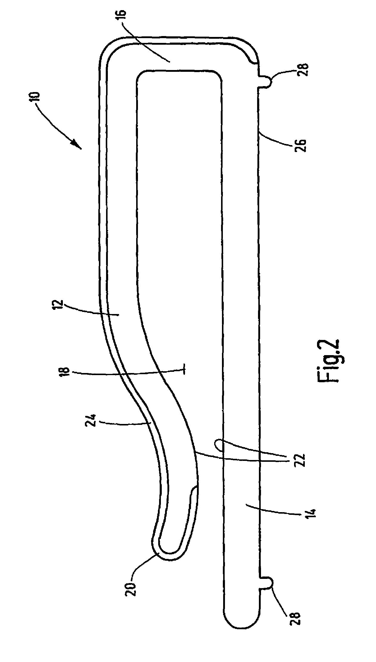
The invention is a device that simplifies and reduces the cost of fastening flexible solar panels to a supporting structure. The device consists of plastic clamping clips that are attached to the structure and form a tight grip on the solar panel. The clamping clips can move relative to the panel, compensating for any expansion or stress on the support structure. The device is easy to install and economical as it uses large-area connecting elements. The upper part of the clamping clip has a flat starting region and a curved middle region to facilitate installation and provide a secure grip on the panel.

Problems solved by technology

The fastening to pertinent supporting structures becomes difficult in view of the mechanical properties of flexible solar panels.
This solution is not entirely satisfactory in that the surface of the supporting structure must be suitable for forming the large-area adhesive connection and because major temperature changes, as can occur with high temperature values, for example, on vehicle bodies, can lead to distortions or warping due to different coefficients of thermal expansion.

Method used


Image

  • Panel arrangement with clamping clip
  • Panel arrangement with clamping clip
  • Panel arrangement with clamping clip

Examples


Embodiment Construction

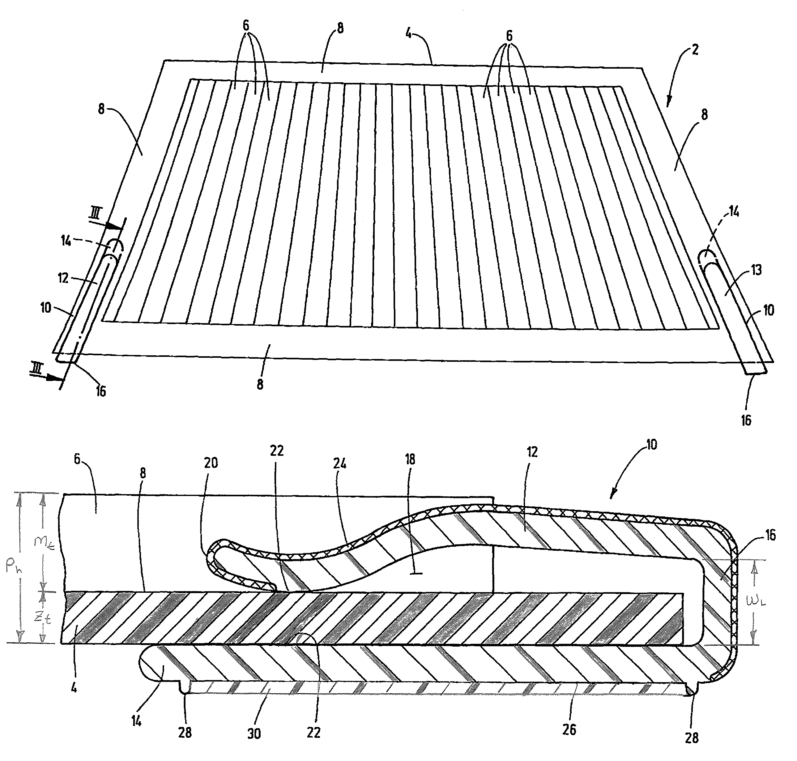
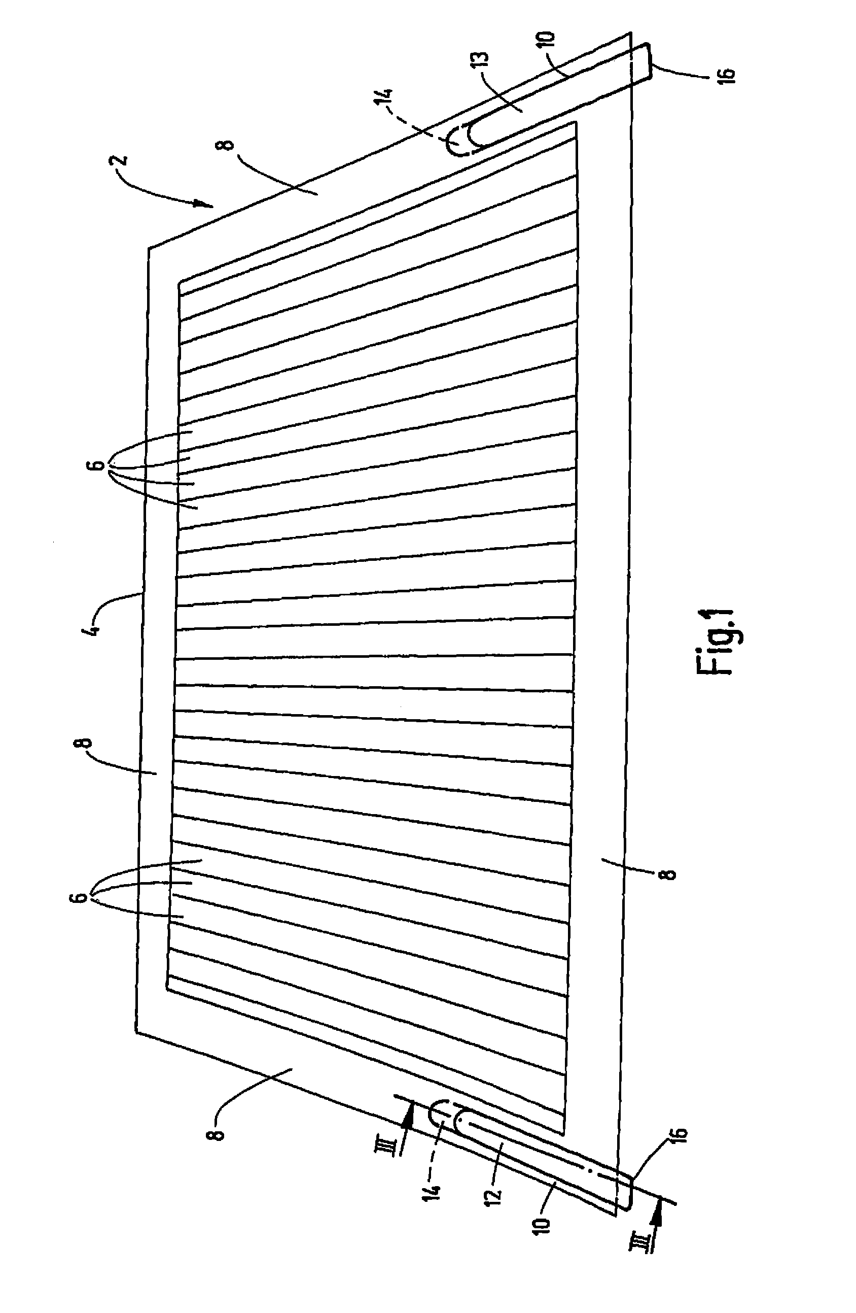
[0019]The invention is explained below using the example of the fastening of a mat-shaped flexible solar panel. The invention is equally well suited to fastening other types of panel-shaped mats. The solar panel 2 in FIG. 1 is on support sheeting 4 fabricated from a preferably burled plastic sheet with a rectangular outline and has an arrangement of a plurality of solar modules 6, of which in FIG. 1 only a few rows are identified in the drawing. In commercial solar modules 6 of this type, the sheeting 4 has dimensions of roughly 55×40 cm and is formed of a weatherproof plastic material such as PMMA or PTFE. The solar modules 6 are arranged on the sheeting 4 such that edge zones 8 remain exposed along the four sides. In the present example, these edge zones 8 are used as holding regions in order to anchor the solar panel 2 on a supporting structure (not shown), in interaction with clamping clips 10 of the device according to the invention. In FIG. 1, only two clamping clips 10 on opp...


PUM

PropertyMeasurementUnit
resilient clamping forcesaaaaaaaaaa
thicknessaaaaaaaaaa
lengthaaaaaaaaaa

Abstract

A device for fastening panel-shaped mats, in particular flexible photovoltaic solar panels, to a supporting structure, has at least one clamping clip (10) in the shape of a section of a plastic profiled body. The clip has opposing profiled limbs (12, 14) forming a clamping space (18) for a holding region (8) of the mat received in it. In the clamping space, the profiled limbs (12, 14) rest with a resilient clamping force against the upper face and the lower face of the holding region (8). The profiled limb (14), which in the clamped state rests against the lower face of the holding region (8) facing the supporting structure, forms a fixing surface (26) on its outer face provided with a connecting element (30) for attaching to the supporting structure.

Description

REFERENCE TO RELATED APPLICATION[0001]This application is a division of U.S. patent application Ser. No. 13 / 201,298, filed May 30, 2012 and entitled Device for Fastening Panel Form Mats, the subject matter of which is hereby incorporated by reference.FIELD OF THE INVENTION[0002]The invention relates to a device for fastening panel-form mats, in particular flexible photovoltaic solar panels, to a supporting structure.BACKGROUND OF THE INVENTION[0003]In the course of the advancing development of solar cells, solar energy recovery has expanded into a plurality of applications. Solar panels are attached to roofs or facades not only for stationary energy recovery for supply of buildings or are set up on corresponding usable surfaces. They also are used on a mobile basis in the form of mat-shaped, flexible solar panels which are also referred to as thin film solar panels. Such flexible solar panels are attached, for example, to exterior surfaces, especially roof surfaces, of motor vehicle...

Claims


Application Information

Patent Timeline
Patent Type & Authority Patents(United States)
IPC IPC(8): F24J2/52A44B18/00E04B2/00E04C2/20E04C2/38E04D5/14F24J2/46H02S20/22H02S20/23
CPCH02S20/23H02S20/22Y02E10/47Y10T24/2758F24S25/61F24S25/613F24S25/634F24S2025/6001F24S2025/6003F24S2025/6004Y02E10/50Y02B10/10E04C2/20E04C2/38E04C2/44A44B18/0073E04D5/145
Inventor POULAKIS, KONSTANTINOS
Owner GOTTLIEB BINDER
Learn More