
Systems and methods for a cooling fluid circuit

a technology of cooling fluid circuit and cooling circuit, which is applied in the direction of engine cooling apparatus, machine/engine, and charge feed system, etc., can solve the problems of engine or egr cooler failure, engine operating temperature, engine or engine thermal efficiency reduction, etc., and achieves lower flow rate, high temperature, thermal efficiency

Active Publication Date: 2016-04-12
GE GLOBAL SOURCING LLC
View PDF16 Cites 2 Cited by
  • Summary
  • Abstract
  • Description
  • Claims
  • Application Information

AI Technical Summary

Benefits of technology

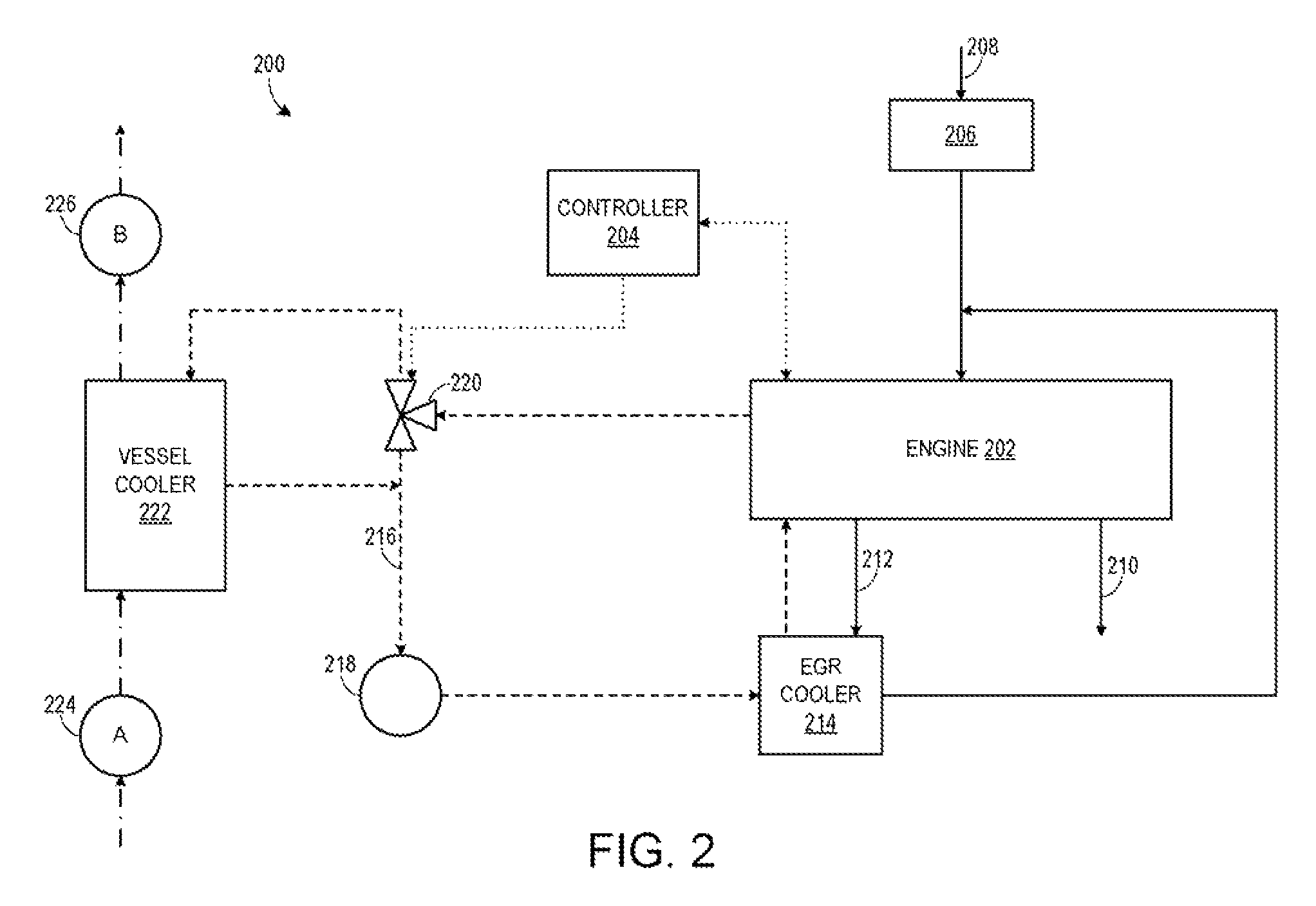
The patent describes a system where a cooling fluid flows through an engine before it passes through an EGR cooler. This results in the cooling fluid being warmer when it enters the engine, which helps to maintain the engine's temperature and improve its thermal efficiency. Additionally, the system requires less cooling fluid and has a lower flow rate compared to a system where the EGR cooler and engine are connected in parallel.

Problems solved by technology

As such, an engine operating temperature may be reduced due to cooler cooling fluid flowing through the engine, thereby reducing a thermal efficiency of the engine.
In this case, degradation of a pressure cap may lead to engine or EGR cooler failure.

Method used


Image

  • Systems and methods for a cooling fluid circuit
  • Systems and methods for a cooling fluid circuit
  • Systems and methods for a cooling fluid circuit

Examples


Embodiment Construction

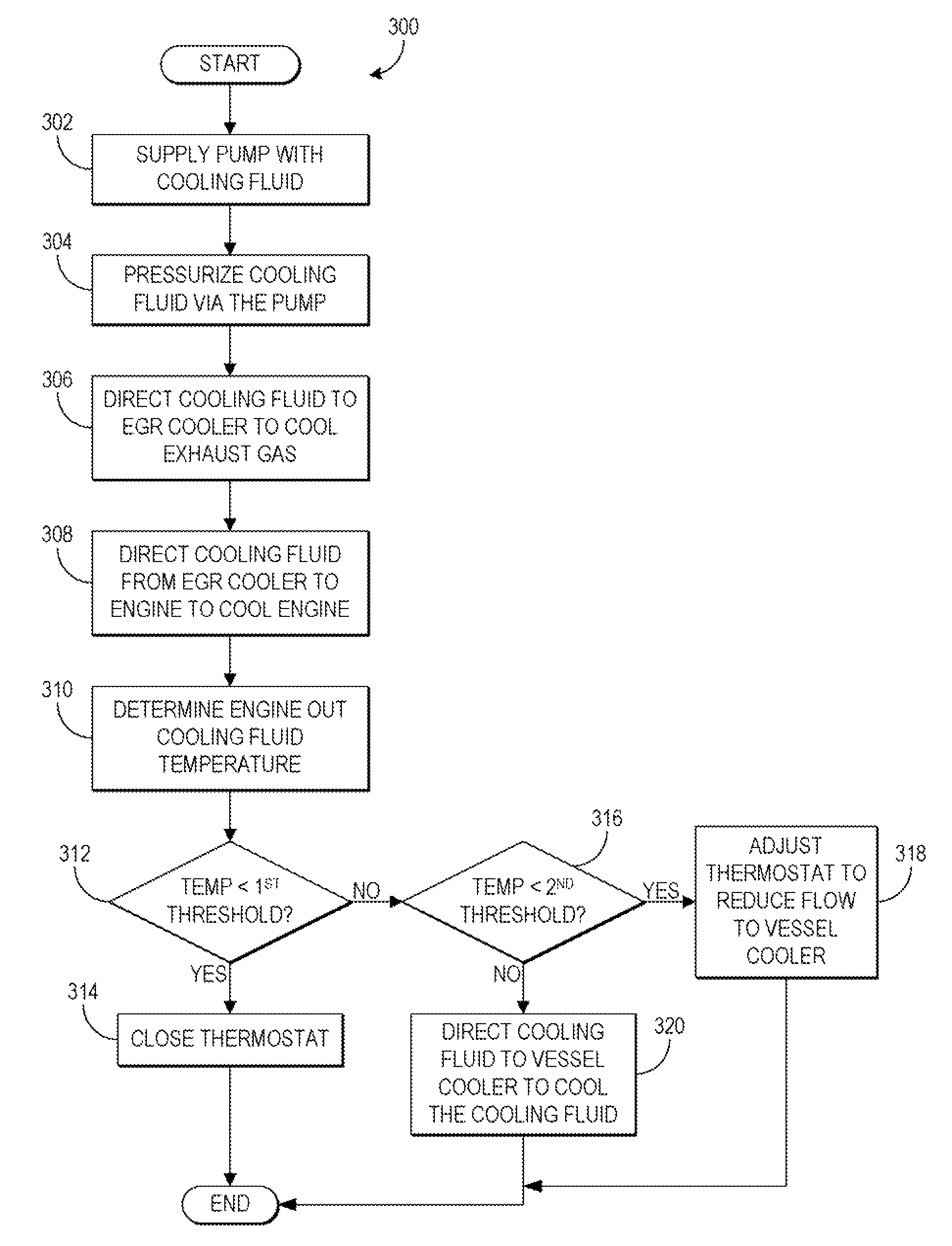
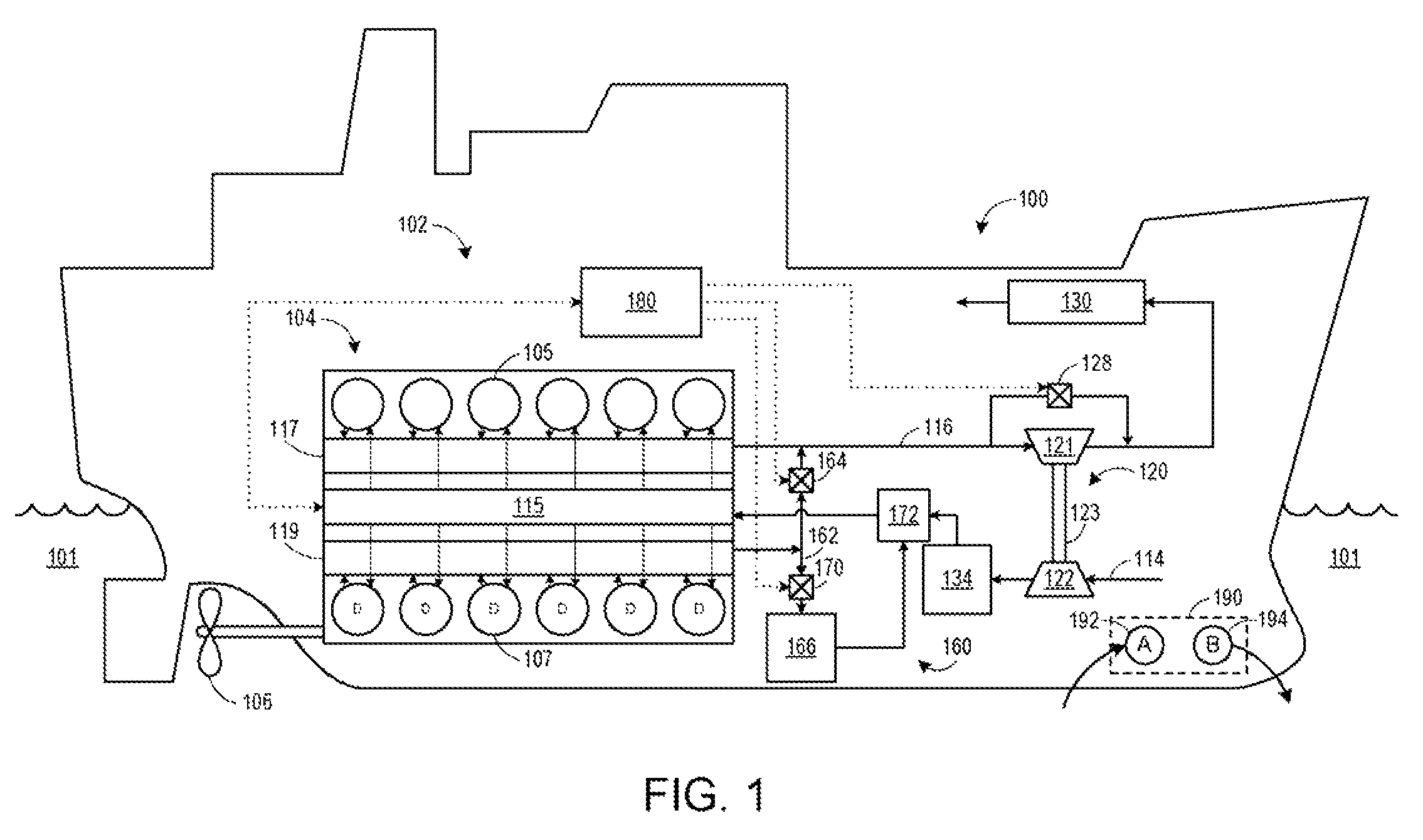
[0011]The following description relates to various embodiments of methods and systems for cooling an engine system. In one exemplary embodiment, a system comprises an exhaust gas recirculation (EGR) cooler and an engine. The system further comprises a cooling fluid circuit in which the EGR cooler and the engine are positioned in series and the EGR is disposed upstream of the engine. In such an embodiment, the cooling fluid cools exhaust gas via the EGR cooler before cooling the engine. In this manner, a temperature of the engine may be maintained at a higher temperature, resulting in improved thermal efficiency. In some embodiments, the system may further include a pump disposed upstream of the EGR cooler in the cooling fluid circuit. In such a configuration, the pump supplies high pressure cooling fluid to the EGR cooler such that the cooling fluid is maintained below its boiling point. Thus, the need for a pressure cap may be reduced and degradation of components of the system due...


PUM


Abstract

Various methods and systems are provided for cooling an engine system. In one example, a system includes an exhaust gas recirculation cooler and an engine. The system further includes a cooling fluid circuit in which the exhaust gas recirculation cooler and the engine are positionable in series with the exhaust gas recirculation cooler disposed upstream of the engine.

Description

FIELD[0001]Embodiments of the subject matter disclosed herein relate to cooling circuits of engine systems.BACKGROUND[0002]Engines may utilize recirculation of exhaust gas from an engine exhaust system to an engine intake system, a process referred to as exhaust gas recirculation (EGR), to reduce regulated emissions. An EGR system may include an EGR cooler to cool the exhaust gas before it enters the intake system. In some examples, the EGR cooler and the engine may be coupled in parallel in a cooling fluid circuit. In such an example, however, an amount of cooling fluid may be increased and / or a flow rate of the cooling fluid may be doubled, for example, as similar flow rates of cooling fluid are sent through the engine and the EGR cooler. In other examples, the EGR cooler may be positioned downstream of the engine in the cooling circuit. As such, an engine operating temperature may be reduced due to cooler cooling fluid flowing through the engine, thereby reducing a thermal effici...

Claims


Application Information

Patent Timeline
Patent Type & Authority Patents(United States)
IPC IPC(8): F01P7/16
CPCF01P7/16F01P2050/06F01P2060/16F02M26/28
Inventor JAYAKAR, VIJAYASELVAN
Owner GE GLOBAL SOURCING LLC
Learn More