Coaxial cable connector and threaded connector
a technology of threaded connectors and coaxial cables, which is applied in the direction of coupling device connections, coupling device details, coupling/disassembly of coupling parts, etc., can solve the problems of unqualified properties of threaded connectors, unqualified electrical connections, and unqualified electrical signals, so as to avoid unqualified electrical connections and good electrical connections
- Summary
- Abstract
- Description
- Claims
- Application Information
AI Technical Summary
Benefits of technology
Problems solved by technology
Method used
Image
Examples
first embodiment
[0080
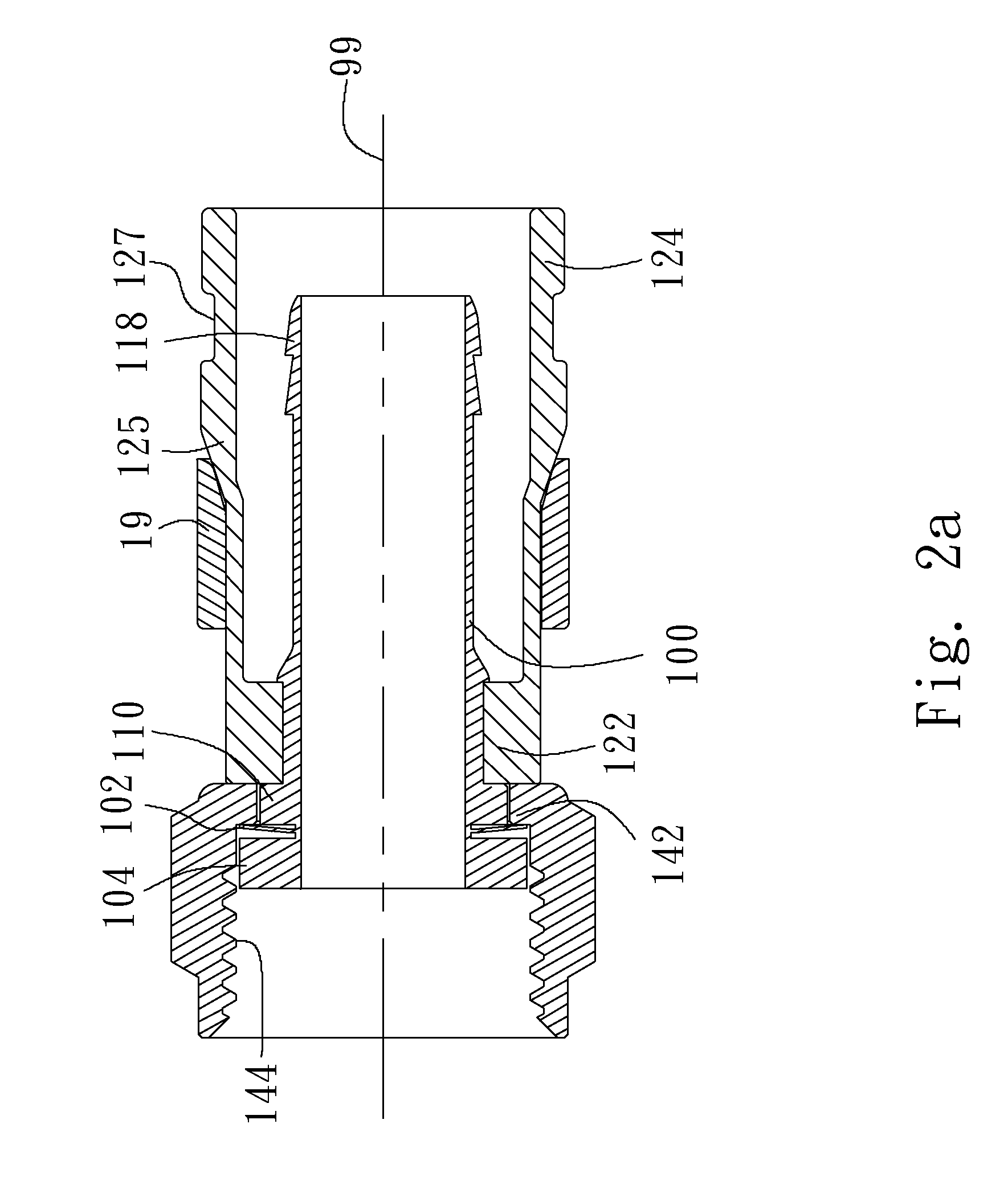
[0081]FIG. 2a is a cross-sectional view showing a coaxial cable connector in accordance with a first embodiment of the present invention. FIG. 2b is a cross-sectional exploded view showing the coaxial cable connector in accordance with the first embodiment of the present invention. FIG. 2c is a perspective view showing an inner sleeve in accordance with the first embodiment of the present invention. FIG. 2i is a front view showing positions of bending lines of two metal sheets relative to the inner sleeve in accordance with the first embodiment of the present invention. Referring to FIGS. 2a, 2b, 2c and 2i, the coaxial cable connector includes an inner sleeve 10, an outer sleeve 12, a nut 14 and a metal ring 19 coaxially arranged with respect to an axis 99 of the inner sleeve 10. Either one of the inner sleeve 10, nut 14 and metal ring 19 may be made of an electrically conductive material, such as copper, iron, silver, nickel, tin, gold, a copper-gold alloy, a copper-tin alloy,...
second embodiment
[0094
[0095]FIG. 3a is a cross-sectional view showing a coaxial cable connector in accordance with a second embodiment of the present invention. FIG. 3b is a cross-sectional view showing an inner sleeve in accordance with the second embodiment of the present invention. FIG. 3f is a front view showing positions of bending lines of two metal sheets relative to the inner sleeve in accordance with the second embodiment of the present invention. Elements in the second embodiment having the same reference number as those in the first embodiment may refer to those illustrated in the first embodiment. Referring to FIGS. 3a, 3b and 3f, the difference between the first and second embodiments is that the inner sleeve 10 in the second embodiment has no second empty gaps 108 illustrated in the first embodiment in the second outer flange 110 at the border between the first outer flange 104 and the second outer flange 110. A blade may be used to cut into the inner sleeve 10 from the first outer fla...
third embodiment
[0103
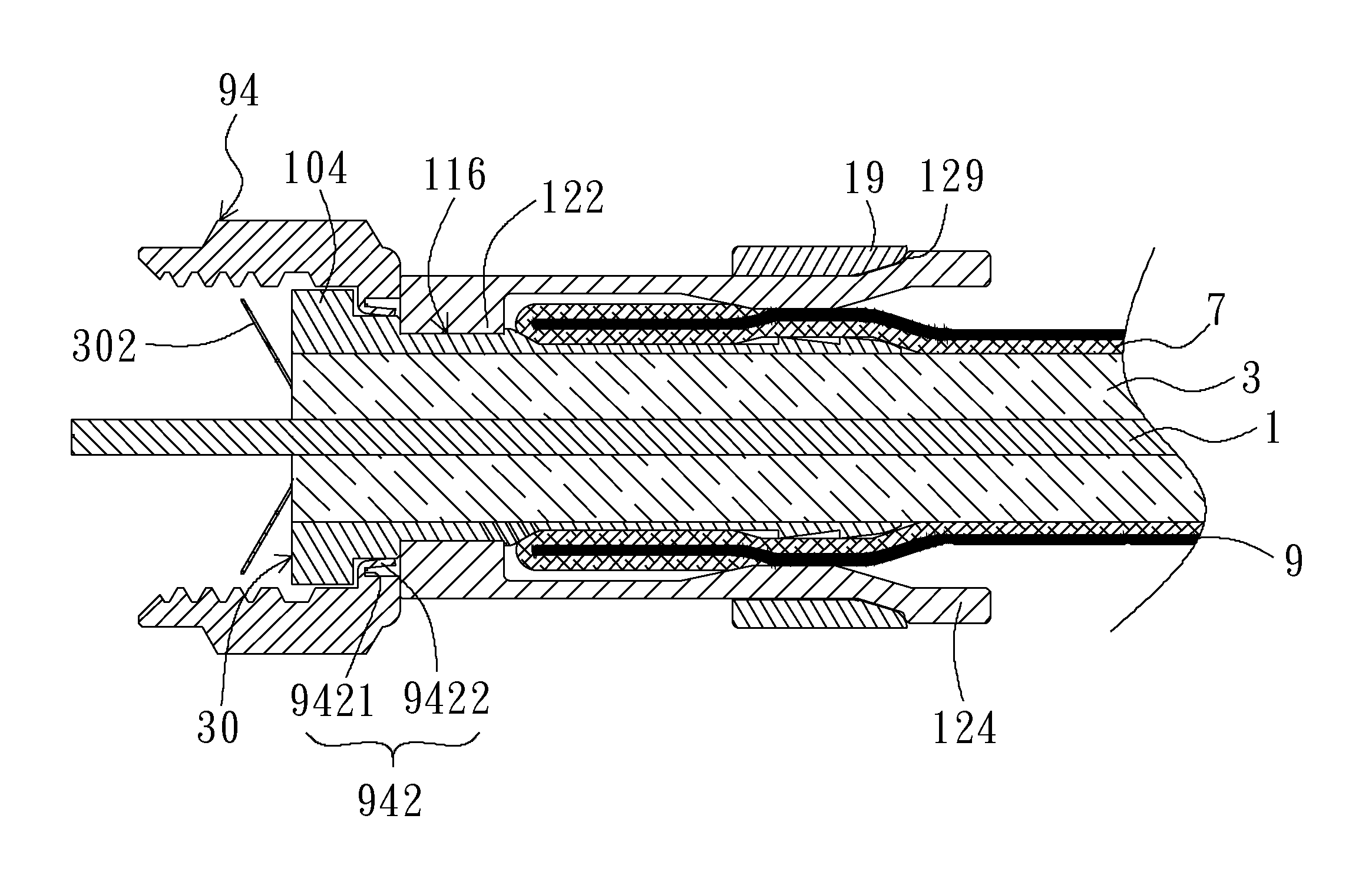
[0104]FIG. 4a is a cross-sectional view showing a coaxial cable connector in accordance with a third embodiment of the present invention. FIG. 4b is a cross-sectional exploded view showing the coaxial cable connector in accordance with the third embodiment of the present invention. FIG. 4c is a perspective view showing an inner sleeve in accordance with the third embodiment of the present invention. FIG. 4i is a front view showing positions of bending lines relative to the inner sleeve with two metal sheets before bent along the bending line in accordance with the third embodiment of the present invention. Elements in the third embodiment having the same reference number as those in the first embodiment may refer to those illustrated in the first embodiment. Referring to FIGS. 4a, 4b, 4c and 4i, the outer sleeve 12, nut 14 and metal ring 19 in accordance with the third embodiment may be referred to those in accordance with the first embodiment. The inner sleeve 30 in accordance...
PUM
 Abstract
Description
Claims
Application Information
 - R&D
- Intellectual Property
- Life Sciences
- Materials
- Tech Scout
- Unparalleled Data Quality
- Higher Quality Content
- 60% Fewer Hallucinations
Browse by: Latest US Patents, China's latest patents, Technical Efficacy Thesaurus, Application Domain, Technology Topic, Popular Technical Reports.
© 2025 PatSnap. All rights reserved.Legal|Privacy policy|Modern Slavery Act Transparency Statement|Sitemap|About US| Contact US: help@patsnap.com


