Cartridge and printing material supply system

Active Publication Date: 2012-10-30
SEIKO EPSON CORP
View PDF19 Cites 68 Cited by
  • Summary
  • Abstract
  • Description
  • Claims
  • Application Information

AI Technical Summary

Benefits of technology

[0083]The cartridge according to the eighteenth aspect has the first cartridge-side restriction element locked by the lever of the printing device. The first cartridge-side restriction element is located on the −Z-axis direction side of the axis of rotation of the lever. This structure does not require any engagement member between the axis of rotation and the operating member of the lever like the cartridge according to the first aspect described above and has the similar advantageous effects to those of the cartridge according to the first aspect. For example, the cartridge according to the eighteenth aspect shortens the distance between the lever and the cartridge, thus allowing size reduction in the X-axis direction of the printing device and the whole printing material supply system including the cartridge and the printing device.
[0084]In the cartridge according to the eighteenth aspect, the first cartridge-side restriction element is provided on the −Z-axis direction side of the axis of rotation of the lever. This enables restriction of the motion of the cartridge in the +Z-axis direction by the lever like the cartridge according to the first aspect and has the similar advantageous effects to those of the cartridge according to the first aspect. For example, this ensures a more stable electrical connection between the cartridge-side terminals and the device-side terminals and reduces the poor continuity.
[0085]According to the embodiment where the cartridge-side terminals comprise a first terminal including a first outer part located at the most +Y-axis direction end; and a second terminal including a second outer part located at the most −Y-axis direction end, wherein the first cartridge-side restriction element is located not outside but inside a range between the first outer part and the second outer part in the Y-axis direction, the first cartridge-side restriction element is located not outside but inside the range between the first outer part and the second outer part. This enables fine adjustment of the direction of the sloped surface with the cartridge-side terminals provided thereon, like the cartridge according to the first embodiment. Even when the position of each of the device-side terminals or the slope of the first cartridge-side restriction element varies due to the manufacturing error, such fine adjustment of the direction of the sloped surface ensures the stable electrical connection between the cartridge-side terminals and the device-side terminals.
[0086]According to the embodiment where the first cartridge-side restriction element is provided at a specific position close to a board end and is located on the −Z-axis direction side of the axis of rotation of the lever, the board end being located on the +Z-axis direction side of the surface of the circuit board, the first cartridge-side restriction element is provided at the position close to the board end located on the +Z-axis direction side. In other words, the first cartridge-side restriction element is arranged as close as possible to the cartridge-side terminals. Since the first cartridge-side restriction element is locked by the lever, the periphery of the first cartridge-side restriction element has substantially no position shift by application of an external force to the cartridge. Providing the cartridge-side terminals at the location of extremely small position shift effectively prevents the positional misalignment of the respective cartridge-side terminals relative to the cartridge mounting structure, thus maintaining the stable electrical connection between the cartridge-side terminals and the device-side terminals.
[0088]A printing material supply system, comprising a printing device; and the cartridge according to any one of the first aspect to the eighteenth aspect, the printing device comprising a cartridge mounting structure configured to have: (i) a device-side bottom wall member; (ii) a first device-side side wall member provided to intersect the device-side bottom wall member; and (iii) a second device-side side wall member provided to intersect the device-side bottom wall member and to be opposed to the first device-side side wall member; a printing material supply tube structured to have a base end provided on the device-side bottom wall member and a peripheral end to be connected with the cartridge and configured to supply a printing material contained in the cartridge to a head; a plurality of device-side terminals provided in a device-side corner section where the device-side bottom wall member intersects the first device-side side wall member; and a lever provided on the first device-side side wall member in a rotatable manner to be used for attachment and detachment of the cartridge to and from the printing device, wherein a Z axis represents an axis parallel to a central axis C of the printing material supply tube, an X axis represents an axis, along which the printing material supply tube and the device-side terminals are arrayed and which is orthogonal to the Z axis, and a Y axis represents an axis orthogonal to both the Z axis and the X axis, wherein a +Z-axis direction represents a direction along the Z axis going from the base end to the peripheral end of the printing material supply tube, a −Z-axis direction represents a reverse direction to the +Z-axis direction, a +X-axis direction represents a direction along the X axis going from the printing material supply tube to the device-side terminals, a −X-axis direction represents a reverse direction to the +X-axis direction, a +Y-axis direction represents a direction along the Y axis going to one end, and −Y-axis direction represents a direction along the Y axis going to the other end, wherein the device-side terminals are in contact with the cartridge to apply a force to the cartridge in a specified direction including the +Z-axis direction component in an attached state of the cartridge to the cartridge mounting structure, and the lever has an operating member at the +Z-axis direction end and a first device-side restriction element at the −Z-axis direction end to lock the cartridge and thereby restrict motion of the cartridge in the +Z-axis direction, the lever rotating about a specified position between the operating member and the first device-side restriction element as an axis of rotation.
[0089]The printing material supply system according to the nineteenth aspect includes the cartridge in accordance with any one of the first aspect to the eighteenth aspect, so as to allow size reduction of the printing material supply system in both the X-axis direction and the Z-axis direction and reduce the possibility that the first device-side restriction element is unlocked from the first cartridge-side restriction element. This ensures the stable electrical connection between the cartridge-side terminals and the device-side terminals and reduces the poor continuity.

Problems solved by technology

Such a large lever results in a larger cartridge, which can also result in a large-size printer, in which the cartridge is attached to and detached from, as well as bulky packaging for transportation and distribution of the cartridges, which in turn increases transportation and parts costs.
The ink cartridges in the carriage undergo great acceleration force with each change in scan direction, in addition to other vibration generated during printing operations.
With this configuration, the material used to produce the cartridge is limited to a material with sufficient moldibility for making this configuration, and also with sufficient flexibility and durability that is needed for the lever to elastically deform during engagement and disengagement with the printer.
Such plastic deformation of the lever may cause positional misalignment between cartridge-side terminals and printer terminals, which could result in poor electrical communication.
Plastic deformation also reduces the durability of the lever.
Because the engagement configuration disclosed in U.S. Pat. No. 6,276,780 includes this inherent risk of the cartridge becoming separated from the printer, it is not suitable for use with the configurations disclosed in U.S. Publication No. 2005 / 0151811, which require proper contact between the cartridge terminals and printer terminals.
Metal oxidation, oil, or other non-conductive matter at the outer surface of the metal electrical contacts 54 can become sandwiched between the conductive metal of the cartridge and printer electrical contacts, possibly hindering electrical communication between the cartridge and the printer.
When the printer electrodes 106 scrape against the circuit board, they can damage this insulation so that fragments of the insulation flake away from the circuit board.
The insulation fragments can get caught between the printer electrodes 106 and the cartridge electrodes 7a, and become a cause of poor or otherwise unreliable electrical communication between the printer and the cartridge.
As will be described below, there is no known mechanism to meet these requirements in a fully acceptable manner.
This problem is not limited to a cartridge containing ink for printing but is also commonly found in any of printing devices and / or cartridges configured to supply or eject various other printing materials (for example, toner) as well as ink.
This results in significantly reducing the possibility of plastic deformation of the first cartridge-side restriction element.
In the attached state, the cartridge can be kept at the proper position in the cartridge mounting structure, which maintains normal or good contact between the cartridge-side terminals and the device-side terminals and reduces the possibility of poor continuity.
This reduces the possibility that the first cartridge-side restriction element is uncoupled from the first device-side restriction element.
This reduces the possibility of positional misalignment of the cartridge-side terminals relative to the device-side terminals and reduces the poor continuity between the cartridge-side terminals and the device-side terminals.
Thus the first cartridge-side restriction element reduces the possibility of poor continuity between the cartridge-side terminals and the device-side terminals.
Such moving reduces the possibility that the first cartridge-side restriction element becomes unlocked from the first device-side restriction element.
This structure lowers the possibility of adhesion of the printing material on the cartridge-side terminals, compared with the structure where the ink supply structure is located closer to the third face than the fourth face.
This reduces the poor continuity between the cartridge-side terminals and the device-side terminals.

Method used


Image

  • Cartridge and printing material supply system
  • Cartridge and printing material supply system
  • Cartridge and printing material supply system

Examples


first embodiment

A. First Embodiment

[0156]A-1. General Configuration of Printing Material Supply System

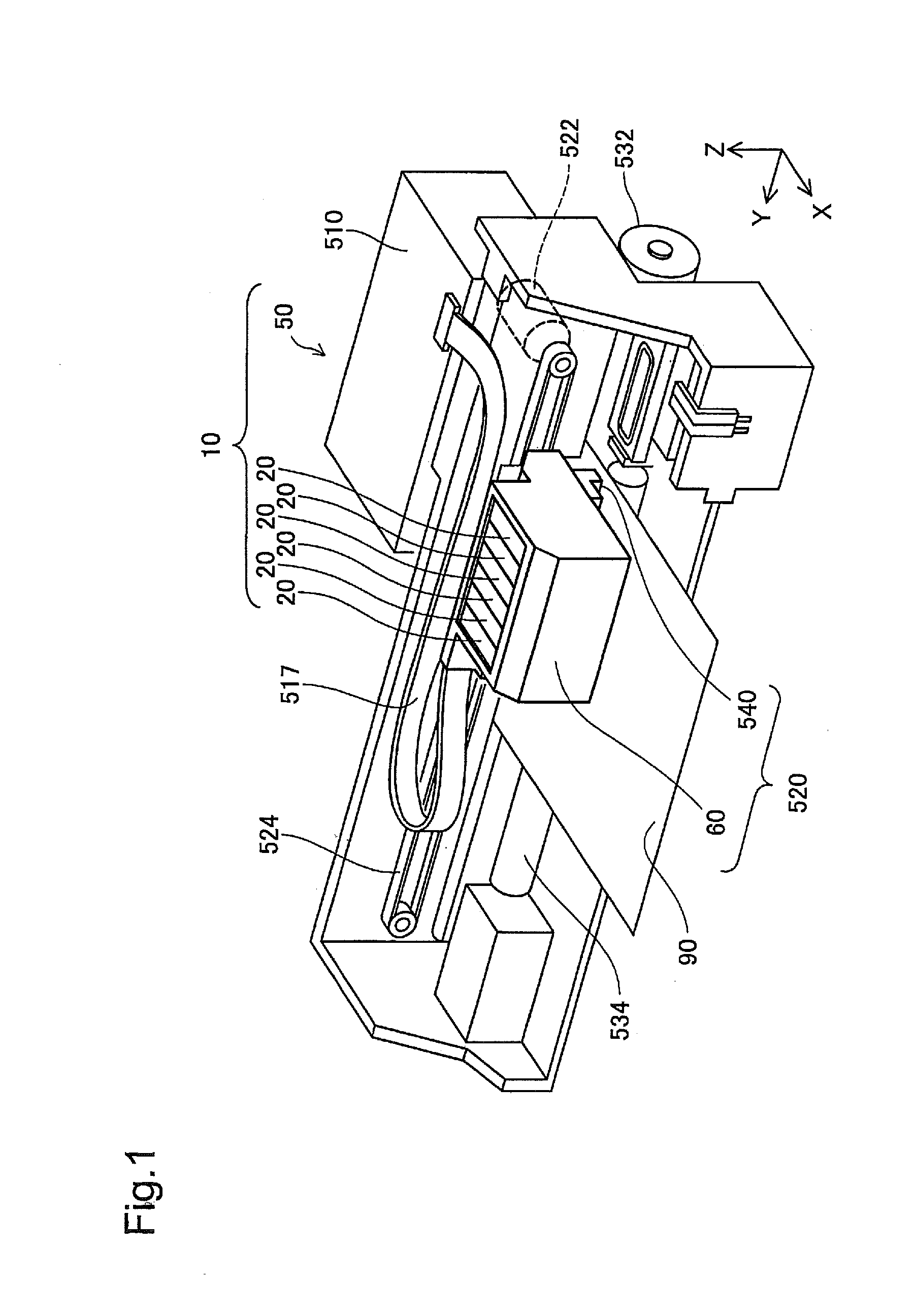
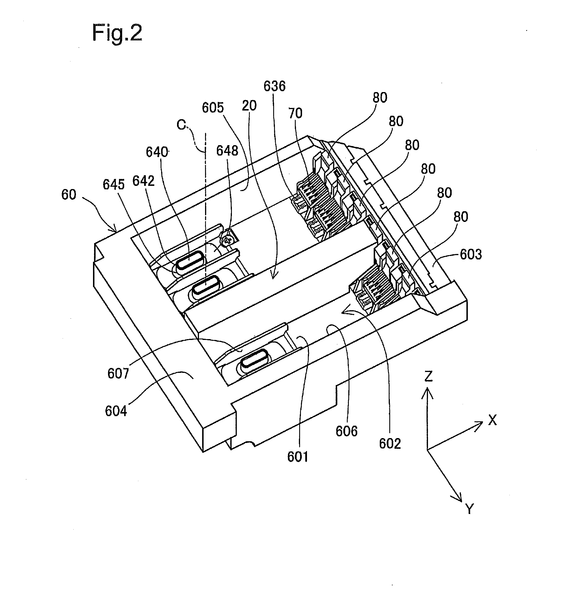
[0157]FIG. 1 is a perspective view illustrating the configuration of a printing material supply system 10. XYZ axes orthogonal to one another are shown in FIG. 1. The XYZ axes in FIG. 1 correspond to the XYZ axes in the other drawings. In the subsequent drawings, the XYZ axes are shown when needed. The printing material supply system 10 includes cartridges 20 and a printer 50 serving as a printing device. In the printing material supply system 10, the cartridges 20 are removably attached to a holder 60 of the printer 50 by the user.

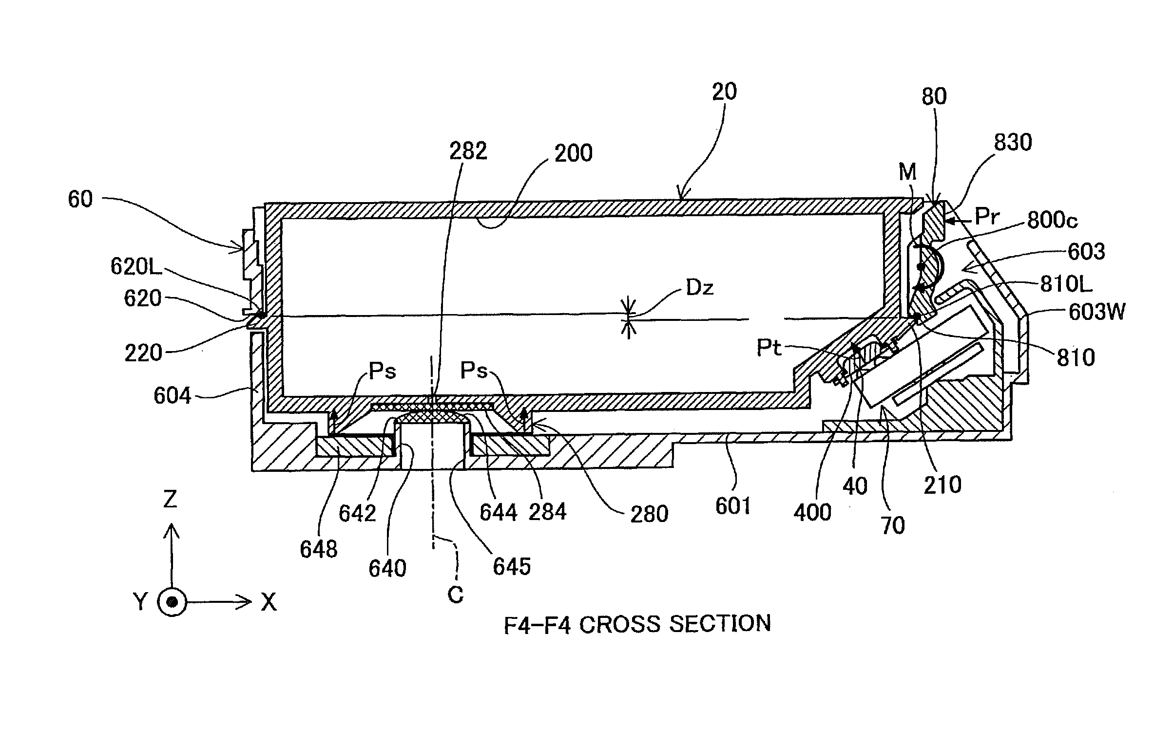
[0158]Each of the cartridges 20 in the printing material supply system 10 contains ink as a printing material. The ink as the printing material contained in the cartridge 20 is supplied through a ink supply structure and a printing material supply tube (described later) to a head 540. According to this embodiment, a plurality of the cartridges 20 are removably attached t...

third embodiment

C. Third Embodiment

[0373]FIG. 34 is a perspective view illustrating the appearance of a cartridge 20b according to a third embodiment. The difference from the cartridge 20 of the first embodiment (FIG. 7) is the size of the cartridge 20b. Otherwise the cartridge 20b of the third embodiment has the same structure as that of the cartridge 20 of the first embodiment. The like elements are expressed by the like symbols and are not specifically explained here. A printer of the third embodiment is adopted for the cartridge 20b but has the same structure as that of the holder 60 and the respective members (for example, lever 80) provided on the holder 60 of the first embodiment.

[0374]The cartridge 20b has the greater dimensions than those of the cartridge 20 of the first embodiment and is capable of containing a greater amount of ink. The cartridge 20b is attachable to a cartridge mounting structure of a large inkjet printer that is capable of printing large paper (e.g., sizes A2 to A0). T...


PUM


Abstract

A cartridge comprises an ink supply structure, a terminal bearing structure, and a first restriction portion. The terminal bearing structure has terminals arranged in a terminal plane which is neither parallel nor perpendicular to a plane defined by a mounting direction leading edge of the ink supply structure, so that the contact portions of the terminals receive a force in a direction opposite from the mounting direction. An engagement portion of the first restriction portion is provided at a position adjacent to the terminal bearing structure.

Description

CROSS REFERENCE TO RELATED APPLICATIONS[0001]This application claims priority to Japanese Patent Application Nos. 2012-3652, 2012-3653, 2012-3694 and 2012-3698 each of which were filed on Jan. 12, 2012, the entire contents of each of which is incorporated by reference herein.BACKGROUND OF THE INVENTION[0002]1. Technical Field[0003]The present invention relates to a cartridge, a combination of a cartridge and a printing device (or portion thereof) and / or a printing material supply system including the cartridge and a printing device.[0004]2. Related Art[0005]Various mechanisms have been proposed for attachment and detachment of a cartridge to a printing device. Examples of such mechanisms are disclosed in U.S. Publication No. 2005 / 0151811 (which corresponds to JP-A-2007-230249), U.S. Pat. No. 7,008,053 (which corresponds to JP-A-2005-022345), U.S. Pat. No. 6,276,780 (which corresponds to JP-A-2002-019142), U.S. Pat. No. 6,955,422, U.S. Pat. No. 6,074,042, and U.S. Pat. No. 7,018,030....

Claims


Application Information

Patent Timeline
IPC IPC(8): B41J2/175
CPCB41J2/1752B41J2/1753B41J2/17553
Inventor KODAMA, HIDETOSHINOZAWA, IZUMIMIZUTANI, TADAHIROMATSUZAKI, KAZUTOSHIHARADA, KAZUMASANAKATA, SATOSHIKAWATA, HIDETAKA
Owner SEIKO EPSON CORP
Why Eureka
Try Eureka