
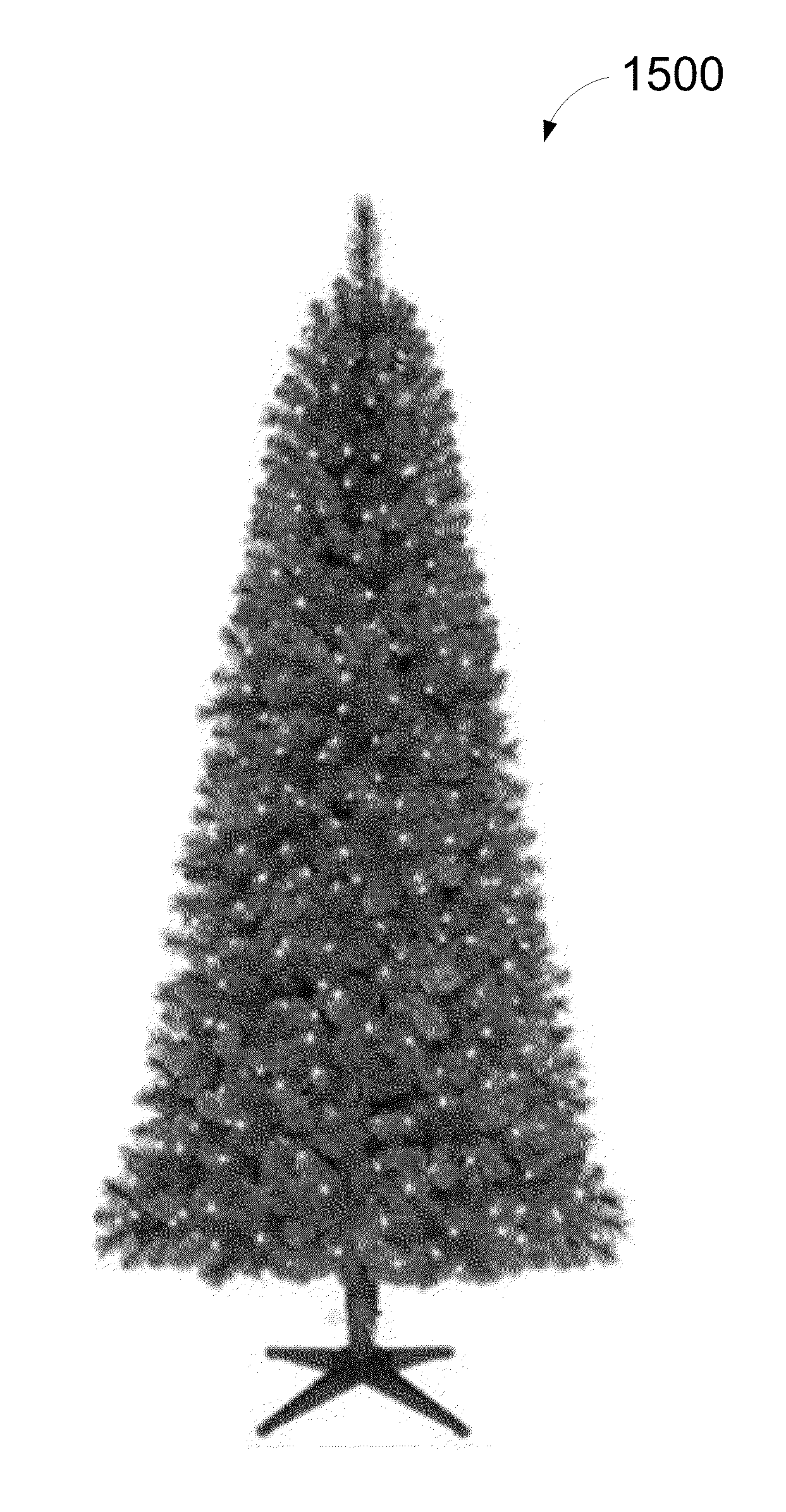
Powered tree construction

a technology of power transfer system and artificial tree, which is applied in the direction of coupling device connection, religious equipment, dwelling equipment, etc., can solve the problems of messy natural trees, high cost of natural trees, waste of environmental resources, etc., and achieves the effect of facilitating the transfer of electrical power, reducing user frustration during the assembly process, and facilitating the assembly of artificial trees

Active Publication Date: 2013-05-02
POLYGROUP MACAU BVI
View PDF24 Cites 77 Cited by
  • Summary
  • Abstract
  • Description
  • Claims
  • Application Information

AI Technical Summary

Benefits of technology

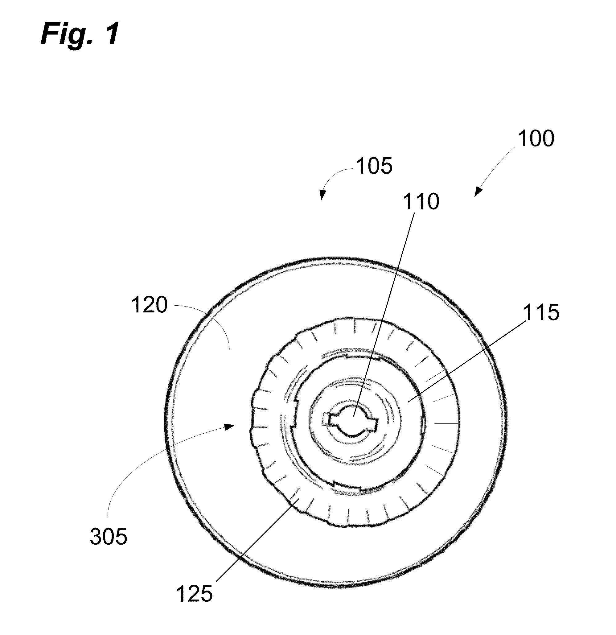
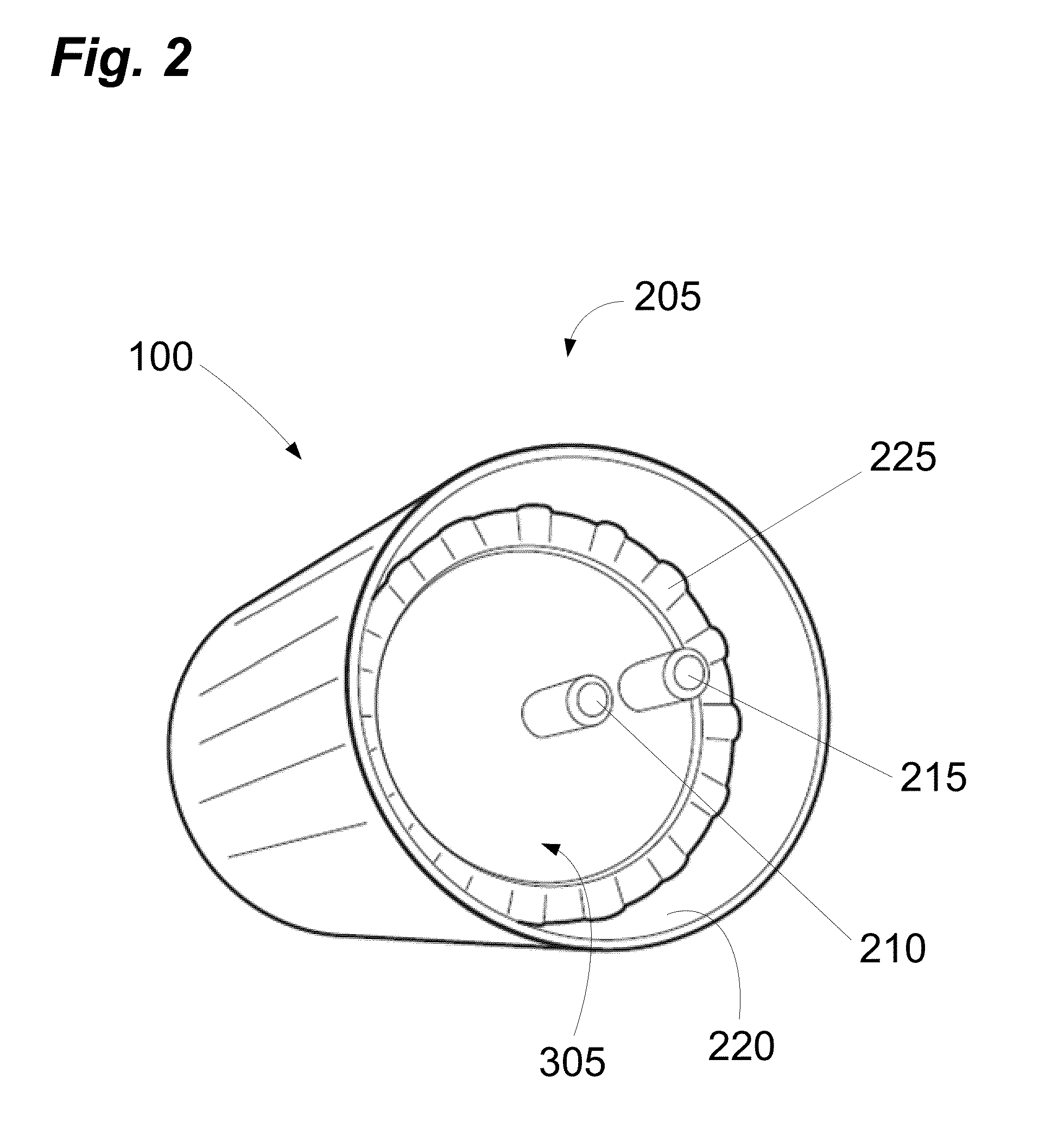
This patent describes a power transfer system for artificial trees that allows neighboring tree trunk sections to be connected without needing to align them during assembly. The system includes a male end with a central prong and a channel prong, and a female end with a central void and a channel void. The male end can be inserted into the female end in a variety of configurations, regardless of their rotational relationship. The first trunk section can also have an inner sleeve that engages with an outer sleeve, and there can be pivot areas to prevent rocking. This system simplifies the assembly process of artificial trees.

Problems solved by technology

Natural trees, however, can be quite expensive and are recognized by some as a waste of environmental resources.
In addition, natural trees can be messy, leaving both sap and needles behind after removal, and requiring water to prevent drying out and becoming a fire hazard.
Because the needles have likely dried and may be quite sharp by this time, removal of the decorations can be a painful process.
In addition, natural trees are often disposed in landfills, further polluting these overflowing environments.
One difficulty encountered during assembly, however, is the rotational alignment of the trunk sections.
This alignment process can be frustrating because it can be difficult for a user to judge whether the prongs will engage the slots when trunk sections are joined together.
It may therefore take several attempts before a user can electrically connect two trunk sections.

Method used


Image

  • Powered tree construction
  • Powered tree construction
  • Powered tree construction

Examples


Embodiment Construction

[0048]Although preferred embodiments of the invention are explained in detail, it is to be understood that other embodiments are contemplated. Accordingly, it is not intended that the invention is limited in its scope to the details of construction and arrangement of components set forth in the following description or illustrated in the drawings. The invention is capable of other embodiments and of being practiced or carried out in various ways. Also, in describing the preferred embodiments, specific terminology will be resorted to for the sake of clarity.

[0049]It should also be noted that, as used in the specification and the appended claims, the singular forms “a,”“an” and “the” include plural references unless the context clearly dictates otherwise. References to a composition containing “a” constituent is intended to include other constituents in addition to the one named.

[0050]Also, in describing the preferred embodiments, terminology will be resorted to for the sake of clarit...


PUM


Abstract

A power transfer system to facilitate the transfer of electrical power between tree trunk sections of an artificial tree is disclosed. The power transfer system can advantageously enable neighboring tree trunk sections to be electrically connected without the need to rotationally align the tree trunk sections. Power distribution subsystems can be disposed within the trunk sections. The power distribution subsystems can comprise a male end, a female end, or both. The male ends can have prongs and the female ends can have voids. The prongs can be inserted into the voids to electrically connect the power distribution subsystems of neighboring tree trunk sections. In some embodiments, the prongs and voids are designed so that the prongs of one power distribution subsystem can engage the voids of another power distribution subsystem without the need to rotationally align the tree trunk sections.

Description

CROSS-REFERENCE TO RELATED APPLICATION AND PRIORITY CLAIM[0001]This application claims the benefit, under 35 U.S.C. §119(e), of U.S. Provisional Patent Application No. 61 / 552,944, filed 28 Oct. 2011, entitled “Powered Tree Construction,” the entire contents and substance of which is incorporated herein by reference in its entirety as if fully set forth below.FIELD OF THE INVENTION[0002]Embodiments of the present invention relate generally to power transfer systems, and, more particularly, to power transfer systems for use with artificial trees, such as artificial Christmas trees.BACKGROUND[0003]As part of the celebration of the Christmas season, many people traditionally bring a pine or evergreen tree into their home and decorate it with ornaments, lights, garland, tinsel, and the like. Natural trees, however, can be quite expensive and are recognized by some as a waste of environmental resources. In addition, natural trees can be messy, leaving both sap and needles behind after rem...

Claims


Application Information

Patent Timeline
Patent Type & Authority Applications(United States)
IPC IPC(8): H01R24/68H01R13/44A41G1/00
CPCH01R24/38A47G33/06F21S2/00H01R13/10H01R31/00H01R33/06H01R2103/00
Inventor LEUNG, CHI YIN ALANTONG, RICKYKWOK, CHI KIN SAMUELHE, CHANG-JUN
Owner POLYGROUP MACAU BVI
Learn More