
Optical rotary transmitter

a rotary transmitter and optical technology, applied in the field of optical rotary transmitters, can solve the problems of high signal attenuation, high cost, complex design, etc., and achieve the effect of simple design

Inactive Publication Date: 2016-03-22
GEORG SIMON OHM HOCHSCHULE
View PDF17 Cites 4 Cited by
  • Summary
  • Abstract
  • Description
  • Claims
  • Application Information

AI Technical Summary

Benefits of technology

The invention relates to a rotary transmitter that allows for reliable transmission of optical signals between rotating parts with a simple design. The design is symmetrical, making it easy to manufacture and ensuring high signal transmission reliability regardless of the angular velocity of the parts. The transmitter can be used to connect optical fibers at distances up to 100 mm. Another design involves additional collimators that allow for multiple signal channels without the need for a multiplex method. The design also ensures better coupling between the two parts due to a more uniform distribution of the reception radiation.

Problems solved by technology

Consequently, this design is very complex.
Such waveguides are not available commercially and are therefore expensive.
With this design, there is high signal attenuation due to uniform distribution of the signals over the entire circumference of the hollow bodies.

Method used


Image

  • Optical rotary transmitter
  • Optical rotary transmitter
  • Optical rotary transmitter

Examples


Embodiment Construction

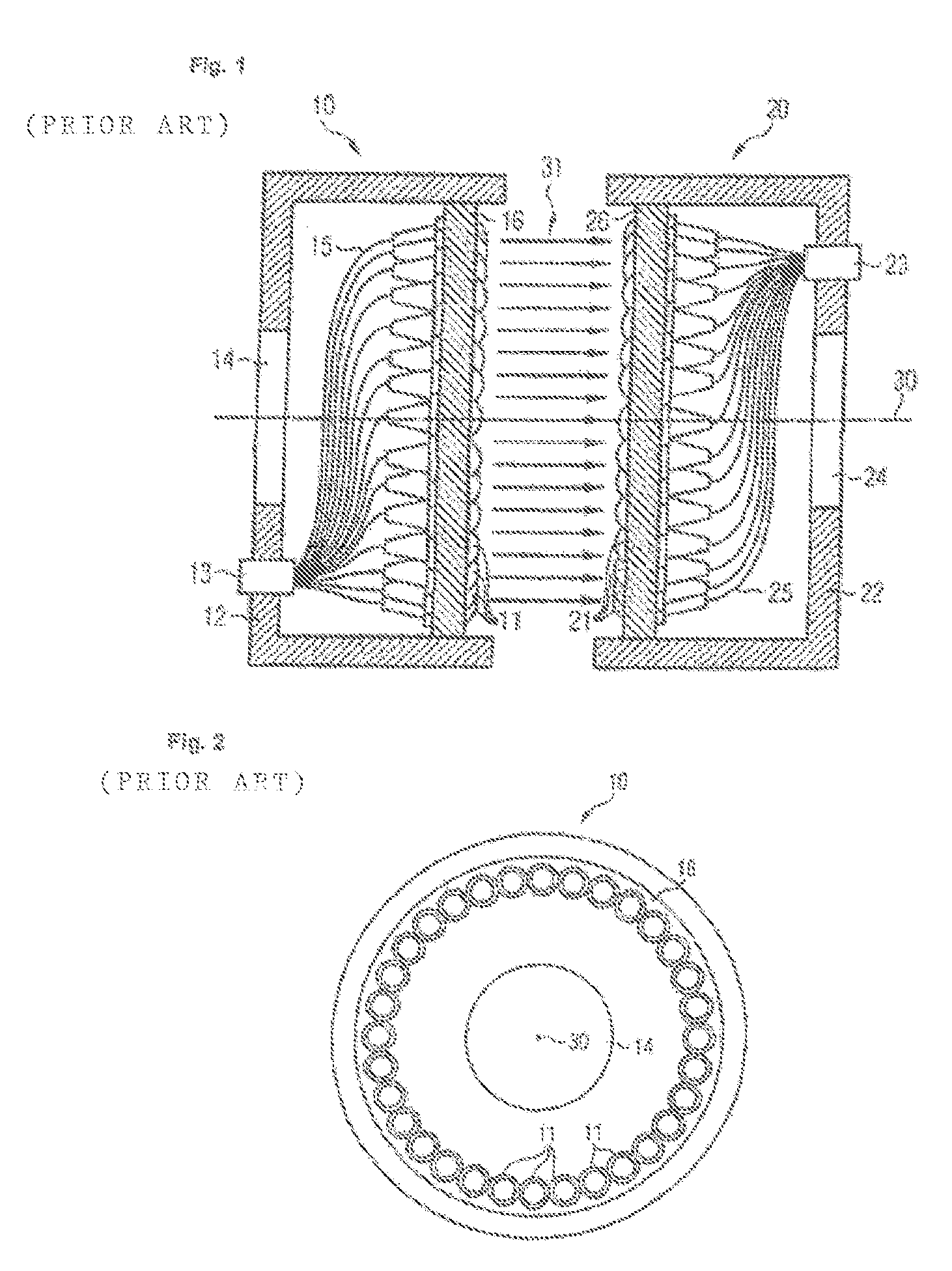
[0036]FIG. 1 shows the essential part of fundamentally any rotator transmitter. It includes a first light coupler 10 and a second light coupler 20. The two light couplers 10, 20 are arranged opposite one another. The first light coupler 10 is assigned to a first part (now shown) of the rotary transmitter, while the second light coupler 20 is assigned to a second part of this rotary transmitter, which can rotate about a shared central axis 30 in relation to the first part. The first light coupler 10 comprises a first collimator arrangement 16 in a housing 12. Similarly, the second light coupler 20 comprises a second collimator arrangement 26 in a housing 22. The first collimator arrangement 16 consists of collimators 11 distributed uniformly and adjacent to one another on the circumference of a circle. The second collimator arrangement 26 consists of similarly arranged collimators 21. The collimators send and receive light essentially in parallel with the shared central axis 30, whic...


PUM


Abstract

An optical rotary transmitter which ensures the reliable transmission of optical signals in conjunction with a comparatively simple construction comprises two parts spaced apart from one another which are rotatable relative to one another about a common centre axis and the first of which comprises a first circular light coupler (10) and the second of which comprises a second circular light coupler (20). The light entrance and light exit surfaces of the two light couplers face one another. Each of the light couplers (10, 20) consists of collimators (11, 21) combined to form a respective collimator arrangement (16, 26), optical coupling elements (15, 25) being connected to said collimators.

Description

CROSS REFERENCES TO RELATED APPLICATIONS[0001]The present application is a 35 U.S.C. § 371 National Stage Patent Application of International PCT Application Serial Number PCT / EP2011 / 02057 having an International filing date of 21 Apr. 2011, which claims priority to German Patent Application Serial No. 102010016773.8 that was filed on 4 May 2010 and German Patent Application Serial No. 102010036174.7 that was filed on 2 Sep. 2010. This Application claims priority to and incorporates by reference the above applications in their entirety for all purposes.BACKGROUND[0002]The invention relates to an optical rotary transmitter having the features of the preamble of claim 1. Such a rotary transmitter may be part of a rotary coupling, for example, or some other device having rotationally movable parts spaced a distance apart from one another and permits unidirectional or bidirectional transmission of optical signals between parts that are rotatable relative to one another independently of ...

Claims


Application Information

Patent Timeline
IPC IPC(8): G02B6/36G02B6/32
CPCG02B6/3604G02B6/36G02B6/32
Inventor POISEL, HANSBLOOS, MARTINZIEMANN, OLAF
Owner GEORG SIMON OHM HOCHSCHULE
Learn More