
Parts with different surface finishes and the procedure to obtain them

a technology of surface finishes and parts, applied in the field of parts with different surface finishes and the procedure to obtain them, can solve the problems of affecting the quality of the product, and the cost of the manufacturing process is considered to be increased, and achieves the effect of high degree of precision and toleran

Active Publication Date: 2016-03-15
PHIBO CAD CAM
View PDF7 Cites 6 Cited by
  • Summary
  • Abstract
  • Description
  • Claims
  • Application Information

AI Technical Summary

Benefits of technology

The invention is about a manufacturing process that allows for the creation of parts with different degrees of precision in different areas. The process involves creating a rough surface finish in certain areas using a sintering process, while other areas are smoothed through a three-dimensional machining process. This roughness improves the ability to attach parts to other materials using cement or similar materials. The process also involves a series of stages that improve the precision and tolerance of the part, resulting in a part with better quality, texture, and finish. Overall, the invention allows for the creation of high-quality parts with low-cost manufacturing.

Problems solved by technology

On the other hand, the amount of discarded material in machining processes such as milling is relatively large, as well as the time invested in the process, which considerably increases the cost of the manufacturing process.

Method used

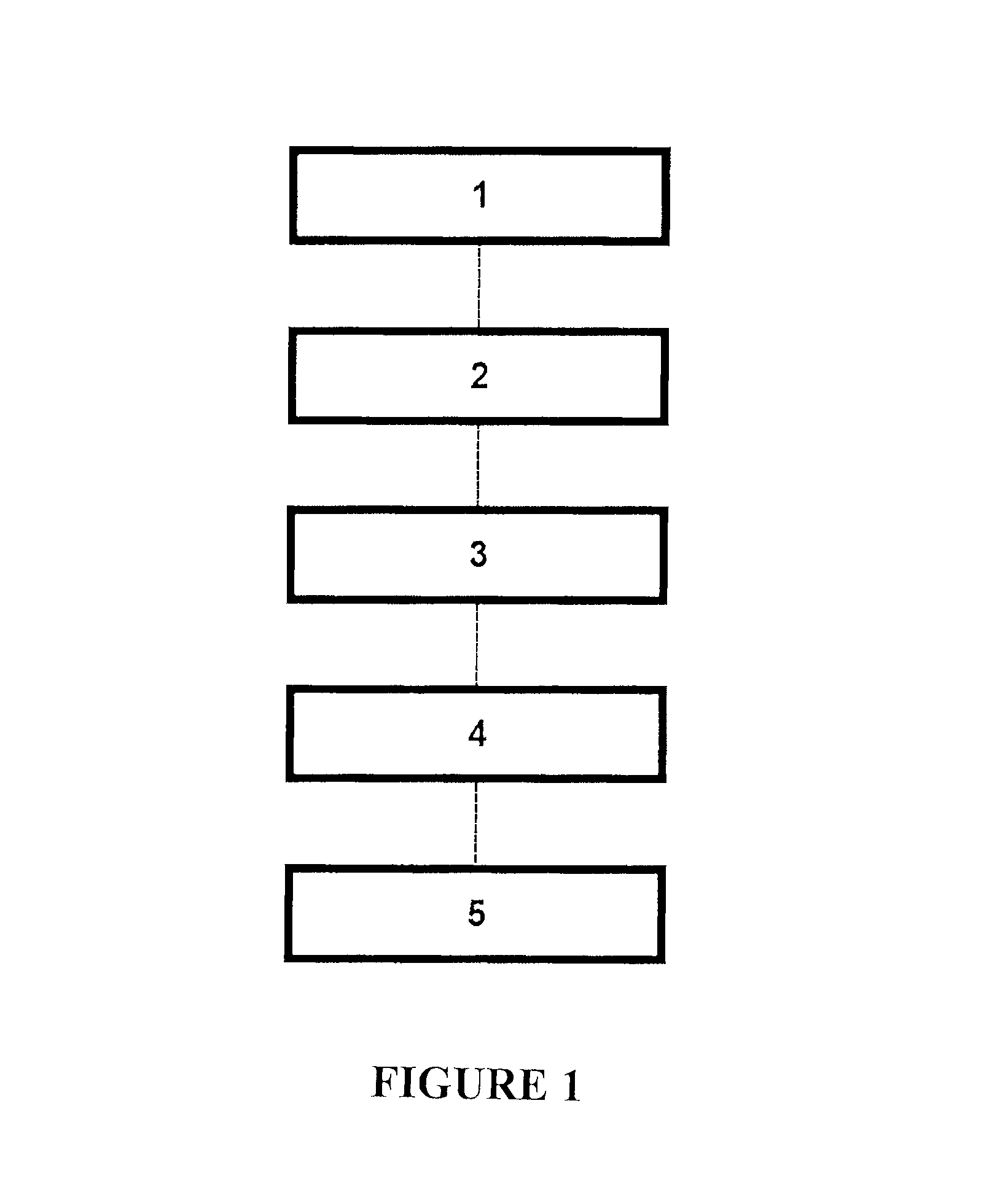
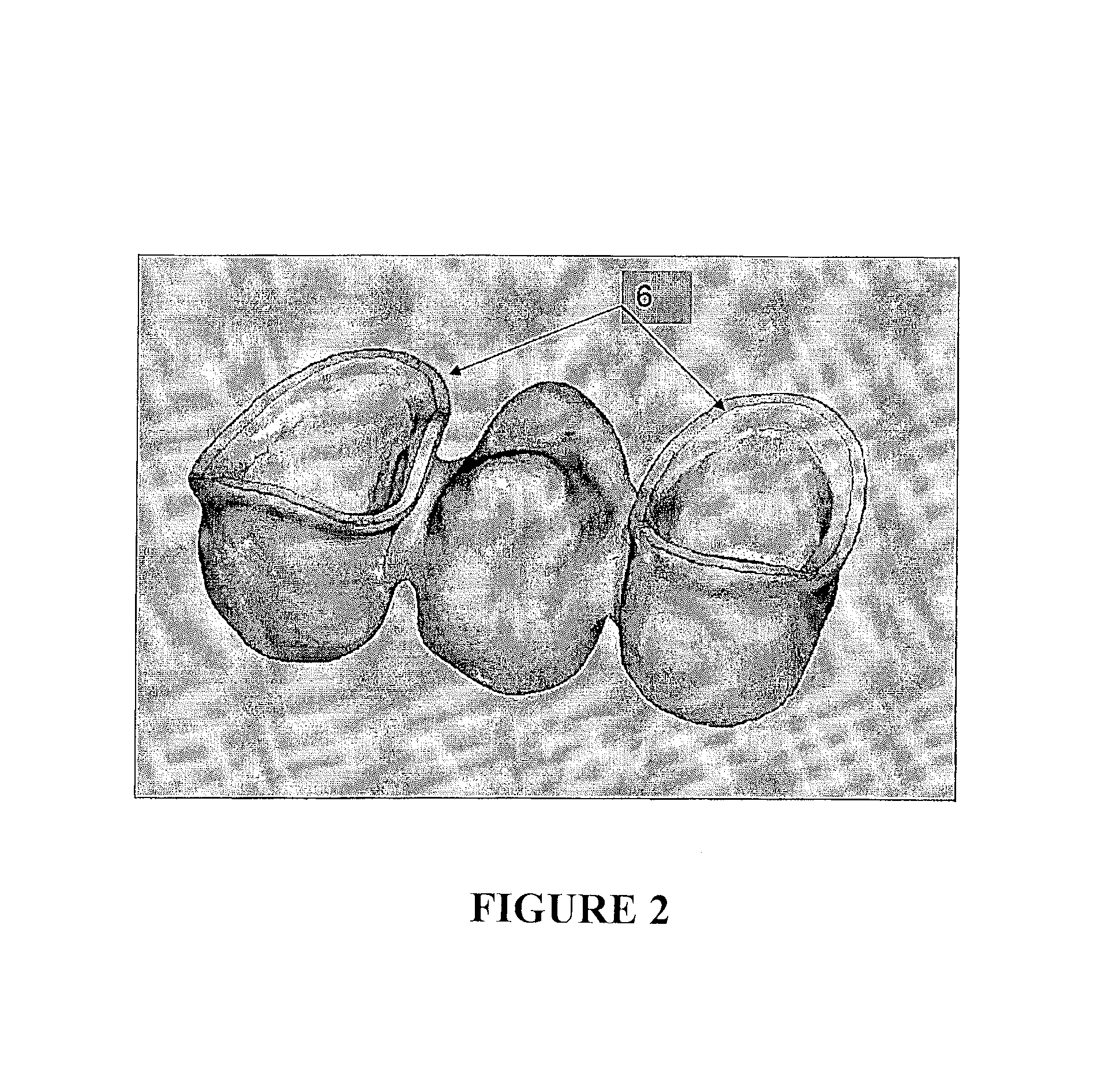
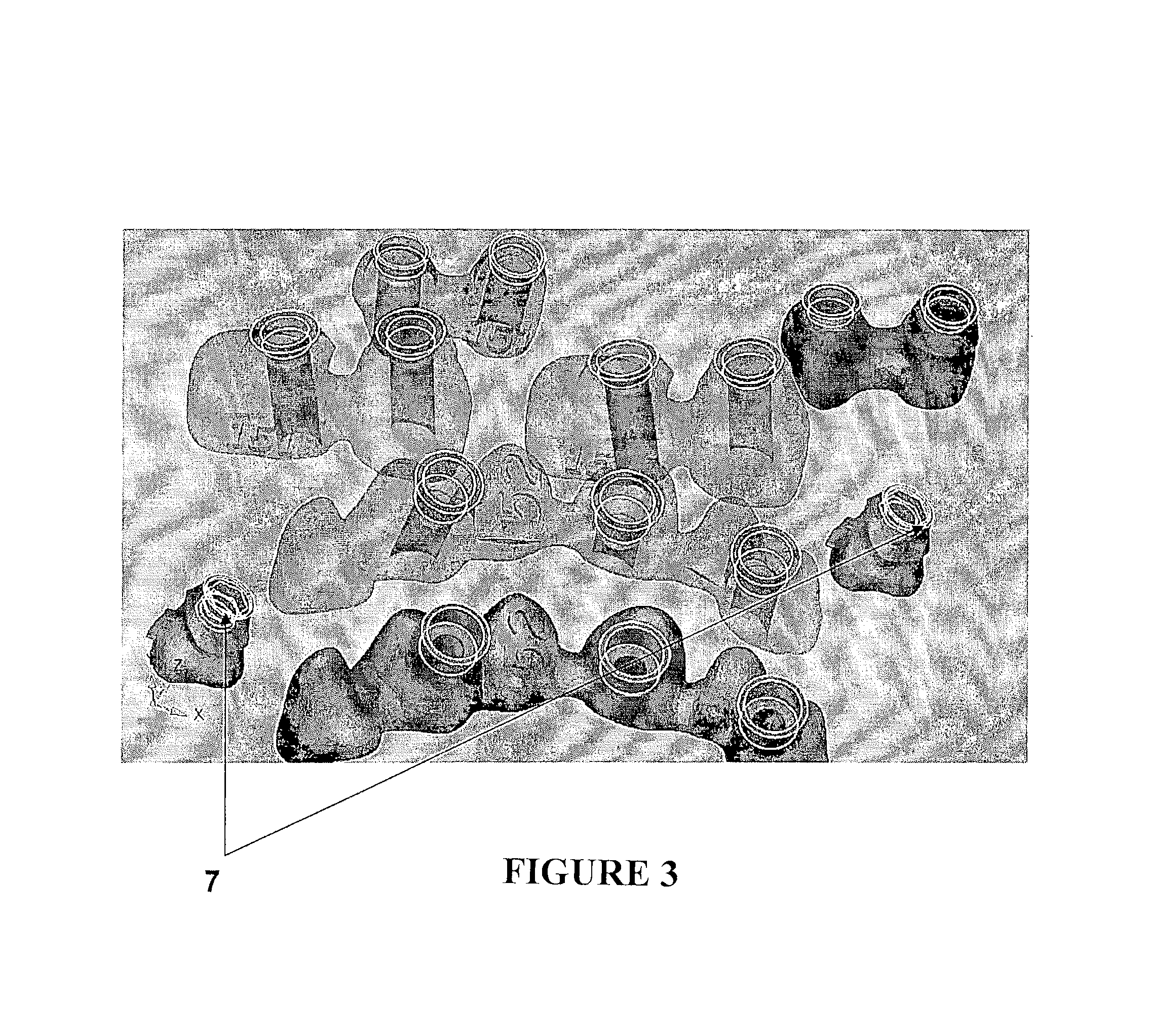

Image

  • Parts with different surface finishes and the procedure to obtain them
  • Parts with different surface finishes and the procedure to obtain them
  • Parts with different surface finishes and the procedure to obtain them

Examples


Embodiment Construction

[0013]First, in order to achieve the goal of obtaining parts manufactured by means of a sintering process that achieves different degrees of precision in different areas, as well as the subsequent advantages derived from the surface finish, the parts that are the object of the invention are manufactured by means of a sintering process and present different surface finishes in areas that are easy to distinguish; in one area a finish obtained by the sintering process with a roughness that is the result of the grain size of the powder used in the sintering process, and in other areas a smooth finish that is the result of subjecting said part to a three-dimensional machining process, thereby obtaining a single part with two perfectly differentiated surface finishes.

[0014]As the parts present a different surface finish in areas that are easy to distinguish, three objectives are achieved:[0015]On one hand, parts that have a high degree of precision in the areas that require a perfect mech...


PUM

PropertyMeasurementUnit
temperatureaaaaaaaaaa
areaaaaaaaaaaa

Abstract

Disclosed are pieces that are produced by sintering, which have well-differentiated surface finish areas including rough areas resulting from the sintering process, the roughness being determined by the size of grain used in sintering, and polished areas that have undergone a three-dimensional machining process. Also, dislosed is a method that, after obtaining a file containing a representation of the piece to be produced, comprises: selecting the parts to be raised; producing the piece by means of sintering; and subsequently subjecting the piece to automatic, semi-automatic or directed programming generation so that, by means of machining, the raised parts are reduced. Consequently, the resulting piece is economical in terms of costs and exhibits a very high degree of precision in the machined areas, a tolerance 9, and improved finish, texture and finishing in the sensitive areas of the piece.

Description

CROSS REFERENCE TO RELATED APPLICATIONS[0001]The present application is a 35 U.S.C. §371 National Phase conversion of PCT / ES2010 / 000367, filed Sep. 3, 2010, which claims benefit of Spanish Application No. P200902005, filed Oct. 16, 2009, the disclosures of which are incorporated herein by reference.OBJECT OF THE INVENTION[0002]The object of this invention is parts with a different surface finish as well as the procedure to obtain them. As the title of the invention states, the parts have different surface finishes in areas that are easily distinguished, with each area thereby providing a series of favourable features for later use.[0003]This invention is characterised by the fact that the parts are manufactured by means of a joint procedure, in general by a sintering process at first, while afterwards certain areas of the part are machined, providing them with a different surface finish.[0004]As regards the manufacturing procedure, this invention is characterised by the fact that th...

Claims


Application Information

Patent Timeline
Patent Type & Authority Patents(United States)
IPC IPC(8): B22F3/24A61C13/00B22F3/12A61C8/00A61C5/77
CPCB22F3/24A61C13/0003A61C13/0004B22F3/12A61C8/0048B22F2003/247Y10T428/24372B33Y10/00B33Y80/00Y02P10/25A61C13/00B22F3/10
Inventor GARCIA APARICIO, JUAN CARLOSAL SINA FONT, FRANCESC
Owner PHIBO CAD CAM
Learn More