
Stationary anterior phased array coil for simultaneous PET-MR imaging

a surface coil and phased array technology, applied in the field of combined petmr system incorporating stationary anterior phased array surface coil, can solve the problems of large coil, reduced signal-to-noise ratio (snr), and mutual annihilation, and achieve the effect of reducing the attenuation of acquired mr signals and pet emissions

Active Publication Date: 2016-03-08
GENERAL ELECTRIC CO
View PDF10 Cites 0 Cited by
  • Summary
  • Abstract
  • Description
  • Claims
  • Application Information

AI Technical Summary

Benefits of technology

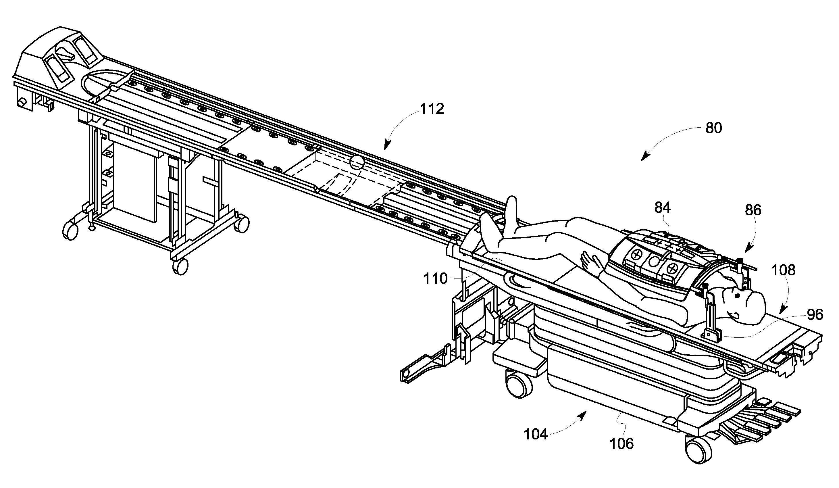
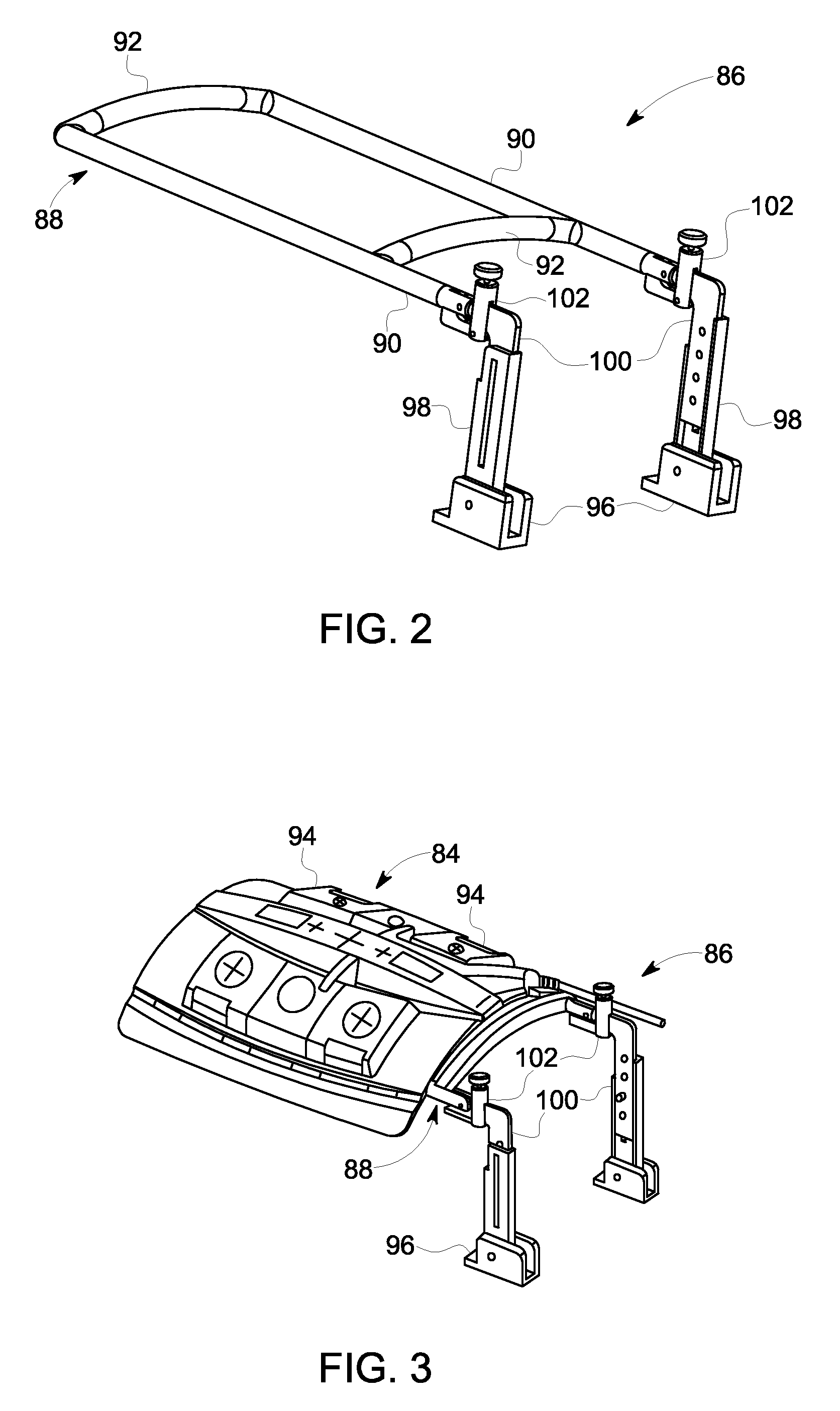
[0011]In accordance with another aspect of the invention, a PET-MR apparatus includes a magnetic resonance imaging (MRI) system configured to acquire MR signals from a patient, the MRI system having a plurality of gradient coils positioned about a bore of a magnet and an RF coil assembly coupled to a pulse generator to emit an RF pulse sequence. The PET-MR apparatus also includes a positron emission tomography (PET) system integrated into the MRI system and having a PET detector positioned on a PET tube encircling the bore, with the PET detector being controlled to acquire PET emissions of the patient. The PET-MR apparatus further includes an anterior surface coil comprising one or more coil elements that is configured to receive MR signals from a volume-of-interest of the patient in the bore resulting from the emitted RF pulse sequence and a coil positioning structure having the anterior surface coil retained thereon, the coil positioning structure being configured to position the anterior surface coil relative to the volume-of-interest and maintain the anterior surface coil in an isolated position from the patient so as to not be in contact with the patient, such that the anterior surface coil is not affected by patient movement or system vibration of the PET-MR apparatus. The coil positioning structure is composed of one or more materials configured to minimize attenuation of the acquired MR signals and PET emissions.

Problems solved by technology

As these positrons travel through the tissues of the subject, they lose kinetic energy and ultimately collide with an electron, resulting in mutual annihilation.
A large coil, however, produces lower signal-to-noise ratio (SNR) if it is also used for reception, mainly because of its greater distance from the signal-generating tissues being imaged.
However, this movement of the surface coil creates a number of challenges with regards to a PET-MR hybrid system, namely because the positioning of ancillary devices on the patient (e.g., surface coils) has never been a requirement for PET imaging since conventional PET imaging systems eliminate all random-placed accessories relative to the patient to reduce artifact.
In employing a surface coil for acquiring MR image data during a PET-MR imaging acquisition, the motion of the surface coil makes the attenuation correction process challenging, as there would be a need to know the position of surface coil real-time during imaging.
And while patient motion correction is not new to either PET or MR, the combination of the two imaging modalities in one simultaneous process creates completely unique challenges.
Namely, conventional “patient breath-holds” or special MR scan sequences that are often employed for stand-alone MR imaging will not be adequate for PET-MR imaging.

Method used


Image

  • Stationary anterior phased array coil for simultaneous PET-MR imaging
  • Stationary anterior phased array coil for simultaneous PET-MR imaging
  • Stationary anterior phased array coil for simultaneous PET-MR imaging

Examples


Embodiment Construction

[0020]An anterior surface coil array positioning system for use in a PET-MR system is provided. The anterior surface coil array positioning system enables vertical adjustment of the coronal positioning of the anterior surface coil array relative to a patient as well as angular adjustment of the anterior surface coil array relative to the coronal plane, such that the coil array can be bridged or cantilevered over a patient that is to be imaged while still isolating the anterior surface coil array from the patient.

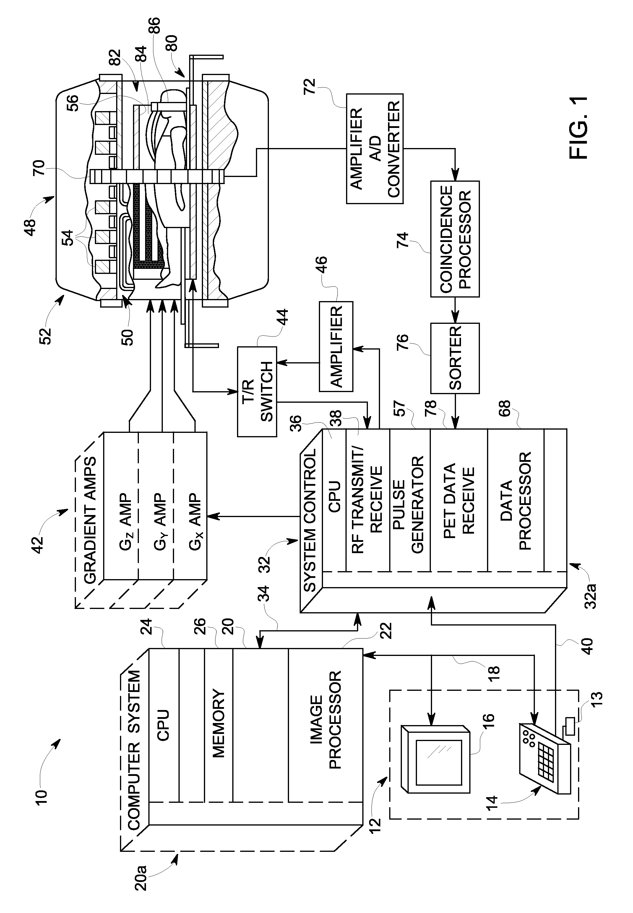
[0021]Referring to FIG. 1, the major components of an exemplary hybrid PET-MR imaging system 10 that may incorporate embodiments of the present invention are shown. The operation of the system may be controlled from an operator console 12 which includes a keyboard or other input device 13, a control panel 14, and a display screen 16. The console 12 communicates through a link 18 with a separate computer system 20 that enables an operator to control the production and display...


PUM


Abstract

A PET-MR apparatus includes an MR imaging system for acquiring MR signals and a PET system for acquiring PET emissions of the patient. The PET-MR apparatus also includes an anterior surface coil configured to receive MR signals from a volume-of-interest of the patient in the bore and resulting from the emitted RF pulse sequence and a coil positioning structure mounted to the PET-MR apparatus and configured to receive the anterior surface coil thereon and position the anterior surface coil proximate to the volume-of-interest of the patient without coming in contact with the patient, with the coil positioning structure being configured to provide both a vertical adjustment of the anterior surface coil relative to a coronal plane of the patient and an angular adjustment of the anterior surface coil relative to the coronal plane of the patient.

Description

BACKGROUND OF THE INVENTION[0001]Embodiments of the invention relate generally to positron emission tomography (PET) and magnetic resonance (MR) imaging, and more specifically, to a combined PET-MR system incorporating a stationary anterior phased array surface coil that can be positioned stationary relative to a patient or patient table, with the coil being constructed so as to enable isolation of the coil from the patient and so as to minimize any affect on PET-MR image acquisition.[0002]PET imaging involves the creation of tomographic images of positron emitting radionuclides in a subject of interest. A radionuclide-labeled agent is administered to a subject positioned within a detector ring. As the radionuclides decay, positively charged photons known as “positrons” are emitted therefrom. As these positrons travel through the tissues of the subject, they lose kinetic energy and ultimately collide with an electron, resulting in mutual annihilation. The positron annihilation resul...

Claims


Application Information

Patent Timeline
Patent Type & Authority Patents(United States)
IPC IPC(8): A61B5/05A61B6/00A61B5/00A61B6/03A61B5/055
CPCA61B6/4417A61B5/0035A61B6/037A61B5/055A61B5/704
Inventor CULVER, CRAIG WILLIAMLORBIECKI, JOHN EDWARDSHAH, BIJAY KAMLESHBHAI
Owner GENERAL ELECTRIC CO
Learn More