
Failure diagnosis method for brake system of vehicle

a technology of failure diagnosis and brake system, which is applied in the direction of braking system, braking components, electric devices, etc., can solve the problems that the braking force generated in the vehicle (and the braking force of the vehicle) does not meet the driver's required braking force, so as to prevent the driver's different feeling, increase the braking distance of the vehicle, and generate a stable braking force

Inactive Publication Date: 2016-03-01
HYUNDAI MOTOR CO LTD +1
View PDF23 Cites 2 Cited by
  • Summary
  • Abstract
  • Description
  • Claims
  • Application Information

AI Technical Summary

Benefits of technology

[0026]Further, after it is precisely decided whether a failure occurs in any one of the braking devices, it is possible to compensate for the braking force of the braking device in which the failure occurs. Accordingly, it is possible to stably generate a braking force corresponding to the driver's required braking force. In addition, it is possible to prevent driver's different feeling and increase in braking distance of the vehicle, which occur in a failure of the conventional braking device.

Problems solved by technology

However, the braking force generated in the vehicle when a failure occurs in a regenerative braking device or friction braking device (i.e., the braking force of the vehicle) does not satisfy the driver's required braking force (does not generate a braking force corresponding to the driver's required braking force).
However, in a case where the failure decision signal of the braking device is not used in the conventional fail safe control method, the compensation for the braking force of the braking device in which the failure occurs is not performed, and therefore, a braking force corresponding to the driver's required braking force is not generated.

Method used


Image

  • Failure diagnosis method for brake system of vehicle
  • Failure diagnosis method for brake system of vehicle
  • Failure diagnosis method for brake system of vehicle

Examples


Embodiment Construction

[0043]Reference will now be made in detail to various embodiments of the present invention(s), examples of which are illustrated in the accompanying drawings and described below. While the invention(s) will be described in conjunction with exemplary embodiments, it will be understood that present description is not intended to limit the invention(s) to those exemplary embodiments. On the contrary, the invention(s) is / are intended to cover not only the exemplary embodiments, but also various alternatives, modifications, equivalents and other embodiments, which may be included within the spirit and scope of the invention as defined by the appended claims.

[0044]The present invention provides a failure diagnosis method for a brake system of a vehicle. Particularly, in the failure diagnosis method, it is possible to decide a failure of a braking device, using an acceleration / deceleration sensor built in the vehicle, so as to provide against a case where it is impossible to use a failure ...


PUM


Abstract

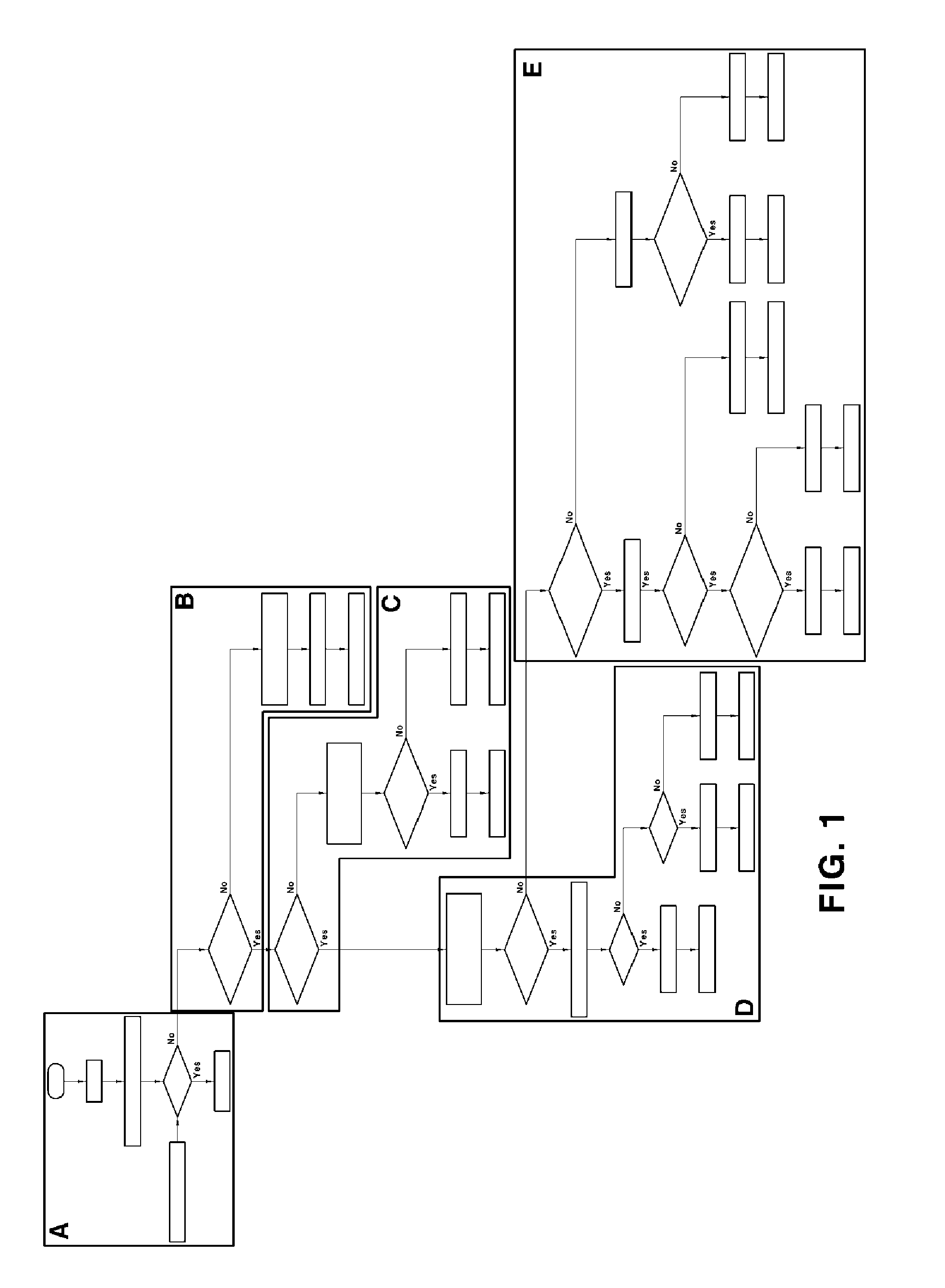
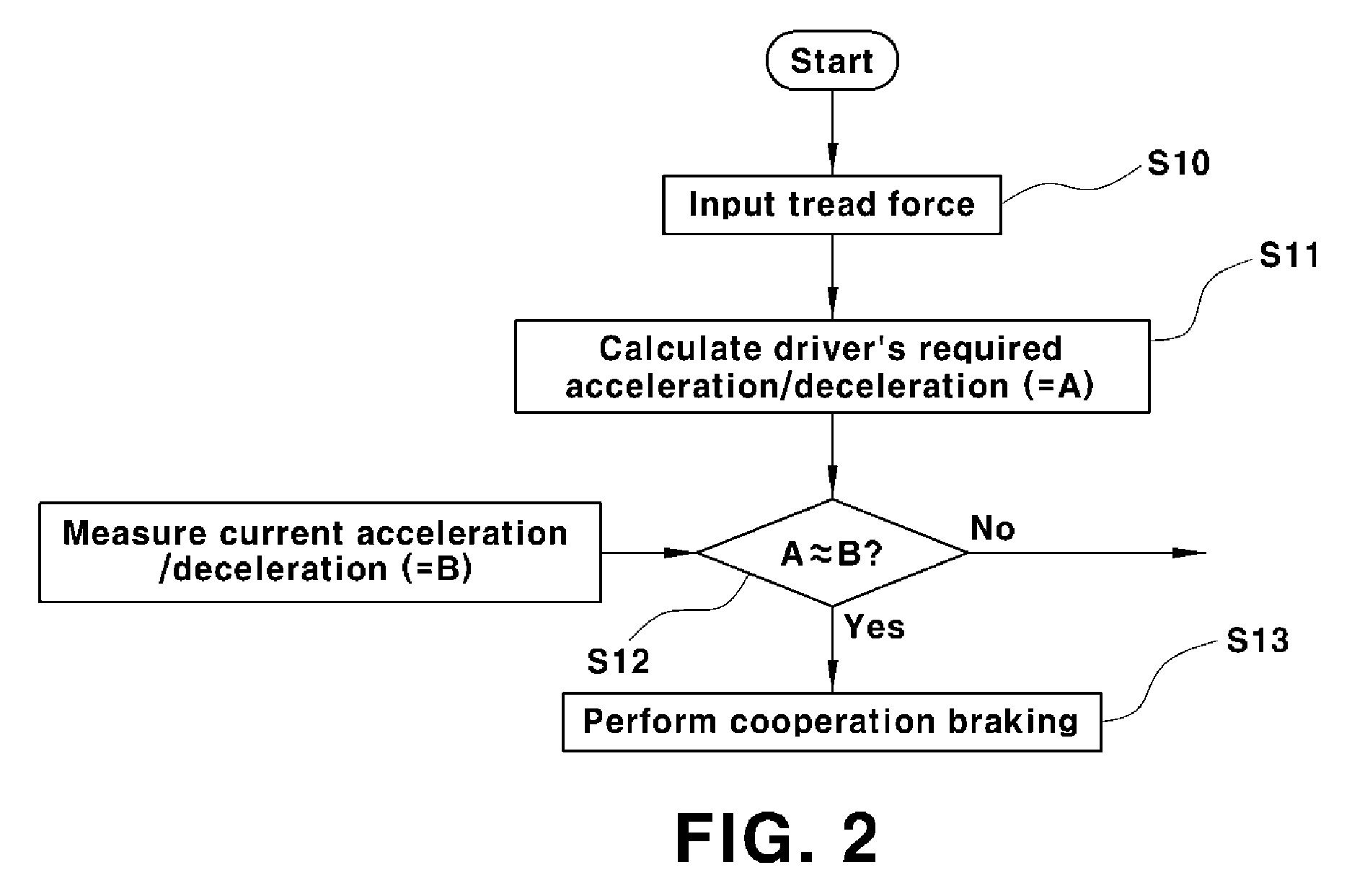
A failure diagnosis method for a brake system of a vehicle determines whether the failure occurs in a regenerative braking device, a front-wheel friction braking device or a rear-wheel friction braking device. The method may include comparing a driver's required acceleration / deceleration with a current acceleration / deceleration of the vehicle, determining that a failure has occurred in the brake system of the vehicle when the driver's required acceleration / deceleration is different from the current acceleration / deceleration of the vehicle and comparing a driver's required braking torque with a regenerative braking maximum torque, and determining that the failure does not occur in the brake system of the vehicle when the driver's required acceleration / deceleration is substantially equal to the current acceleration / deceleration of the vehicle.

Description

CROSS-REFERENCE TO RELATED APPLICATION[0001]The present application claims priority of Korean Patent Application Number 10-2013-0047981 filed Apr. 30, 2013, the entire contents of which application are incorporated herein for all purposes by this reference.BACKGROUND OF INVENTION[0002]1. Field of Invention[0003]The present invention relates to a failure diagnosis method for a brake system of a vehicle driven using an electric motor. More particularly, the present invention relates to a failure diagnosis method for a brake system of a vehicle, in which, when a failure occurs in the brake system of the vehicle, it is decided whether the failure occurs in any one of a regenerative braking device, a front-wheel friction braking device and a rear-wheel friction braking device, which constitute the brake system.[0004]2. Description of Related Art[0005]As known in the art, a green vehicle such as a hybrid vehicle or electric vehicle driven by an electric motor performs regenerative braking...

Claims


Application Information

Patent Timeline
Patent Type & Authority Patents(United States)
IPC IPC(8): B60T17/22B60L3/00B60T8/88B60T13/66B60W20/00B60T1/10B60W50/04
CPCB60T17/221B60L3/0076B60T1/10B60T8/885B60T13/662B60T17/22B60W20/50B60W50/04B60T2270/402B60T2270/413B60T2270/604B60T8/176B60W10/18
Inventor KIM, IN, SUJEONG, JONG, YUNHYUN, DONG, YOONKO, JI, WEONKIM, HYUN, SOO
Owner HYUNDAI MOTOR CO LTD
Learn More