Symbol timing recovery scheme for parallel recording channel systems

a parallel recording channel and parallel recording technology, applied in the field of data storage systems, can solve the problems of reducing snr, bit of information to be lost, tape systems with classical str schemes failing at low snr, etc., and achieve the effect of reducing the rate of cycle slips

Active Publication Date: 2016-02-02
IBM CORP
View PDF8 Cites 3 Cited by
  • Summary
  • Abstract
  • Description
  • Claims
  • Application Information

AI Technical Summary

Benefits of technology

[0008]In one general embodiment, a tape-based data storage system includes a plurality of timing error detectors, where each of the timing error detectors outputs a corresponding timing error detector output signal. The system also includes a loop filter in communication with the plurality of timing error detectors. The loop filter receives a plurality of input signals, wherein each of the input signals is based on a different one of the timing error detector output signals. Further, the system includes a plurality of read channels and a plurality of interpolation filters, where each of the interpolation filters is in communication with a corresponding one of the read channels. Still yet, the system includes an array of transducers, where each of the transducers is in communication with a corresponding one of the read channels. Additionally, the loop filter processes the plurality of input signals, and outputs a different total phase signal for each received input signal, and each of the interpolation filters samples the corresponding read channel based on one of the total phase signals output by the loop filter. Finally, the loop filter processes the plurality of input signals by calculating a phase estimate of the samples, and a skew estimate of the samples, relative to written data. Such a system may experience a reduced rate of cycle slips on one or more of the read channels relative to prior art systems.

Problems solved by technology

However, increasing the track and bit density on recording tape results in problems, such as decreased SNR.
Tape systems with classical STR schemes fail at low SNR due to high cycle slip rates.
A cycle slip may occur when, during the parallel reading of a medium having multiple parallel channels, a timing estimate or timing-error estimate of one or more of the channels is noisy, and the timing erroneously advances by a full bit length, causing a bit of information to be lost.
A cycle slip may also occur when, during the parallel reading of a medium having multiple parallel channels, a timing estimate or timing error of one or more of the channels is noisy, and timing retreats by a full bit length, causing a bit to be erroneously inserted.

Method used


Image

  • Symbol timing recovery scheme for parallel recording channel systems
  • Symbol timing recovery scheme for parallel recording channel systems
  • Symbol timing recovery scheme for parallel recording channel systems

Examples


Embodiment Construction

[0023]The following description is made for the purpose of illustrating the general principles of the present invention and is not meant to limit the inventive concepts claimed herein. Further, particular features described herein can be used in combination with other described features in each of the various possible combinations and permutations.

[0024]Unless otherwise specifically defined herein, all terms are to be given their broadest possible interpretation including meanings implied from the specification as well as meanings understood by those skilled in the art and / or as defined in dictionaries, treatises, etc.

[0025]It must also be noted that, as used in the specification and the appended claims, the singular forms “a,”“an” and “the” include plural referents unless otherwise specified.

[0026]The following description discloses several preferred embodiments of magnetic storage systems, as well as operation and / or component parts thereof.

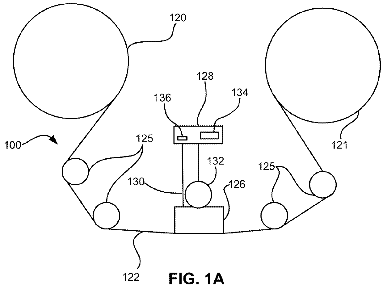
[0027]In one general embodiment, a tape-...


PUM

PropertyMeasurementUnit
widthaaaaaaaaaa
phaseaaaaaaaaaa
total phaseaaaaaaaaaa

Abstract

A method for symbol timing recovery is disclosed. The method comprises receiving a plurality of timing-error estimates for a plurality of read channels, where each of the timing-error estimates corresponds to one of the read channels. The method further comprises calculating a common phase based on the plurality of timing-error estimates, and calculating a skew of a transducer array based on the plurality of timing-error estimates. Finally, the method comprises calculating a different total phase estimate for each read channel based on the calculated common phase and the calculated skew of the transducer array.

Description

BACKGROUND[0001]The present invention relates to data storage systems, and more particularly, this invention relates to symbol timing recovery on magnetic media having parallel tracks that are written, and read, simultaneously.[0002]In magnetic storage systems, magnetic transducers read data from and write data onto magnetic recording media. Data is written on the magnetic recording media by moving a magnetic recording transducer to a position on the media where the data is to be stored. The magnetic recording transducer then generates a magnetic field, which encodes the data into the magnetic media. Data is read from the media by similarly positioning the magnetic read transducer and then sensing the magnetic field of the magnetic media. Read and write operations may be independently synchronized with the movement of the media to ensure that the data can be read from and written to the desired location on the media.[0003]In some instances of tape recording, multiple (e.g., 4, 8, 16...

Claims


Application Information

Patent Timeline
Patent Type & Authority Patents(United States)
IPC IPC(8): G11B20/20G11B5/00G11B5/02
CPCG11B5/02G11B5/00826G11B5/584G01R31/31922H04L25/05G11B5/00813G11B5/29G11B20/10037G11B20/10046G11B20/10259
Inventor FURRER, SIMEONHUTCHINS, ROBERT A.JELITTO, JENSLANTZ, MARK A.
Owner IBM CORP
Why Eureka
Try Eureka