Power converter
a power converter and converter technology, applied in the field of power converters, can solve the problems of complex control circuits, inability to utilize the features of the capacitorless method, etc., and achieve the effect of good responsivity to inductive loads
- Summary
- Abstract
- Description
- Claims
- Application Information
AI Technical Summary
Benefits of technology
Problems solved by technology
Method used
Image
Examples
first embodiment
[0105](First Embodiment)
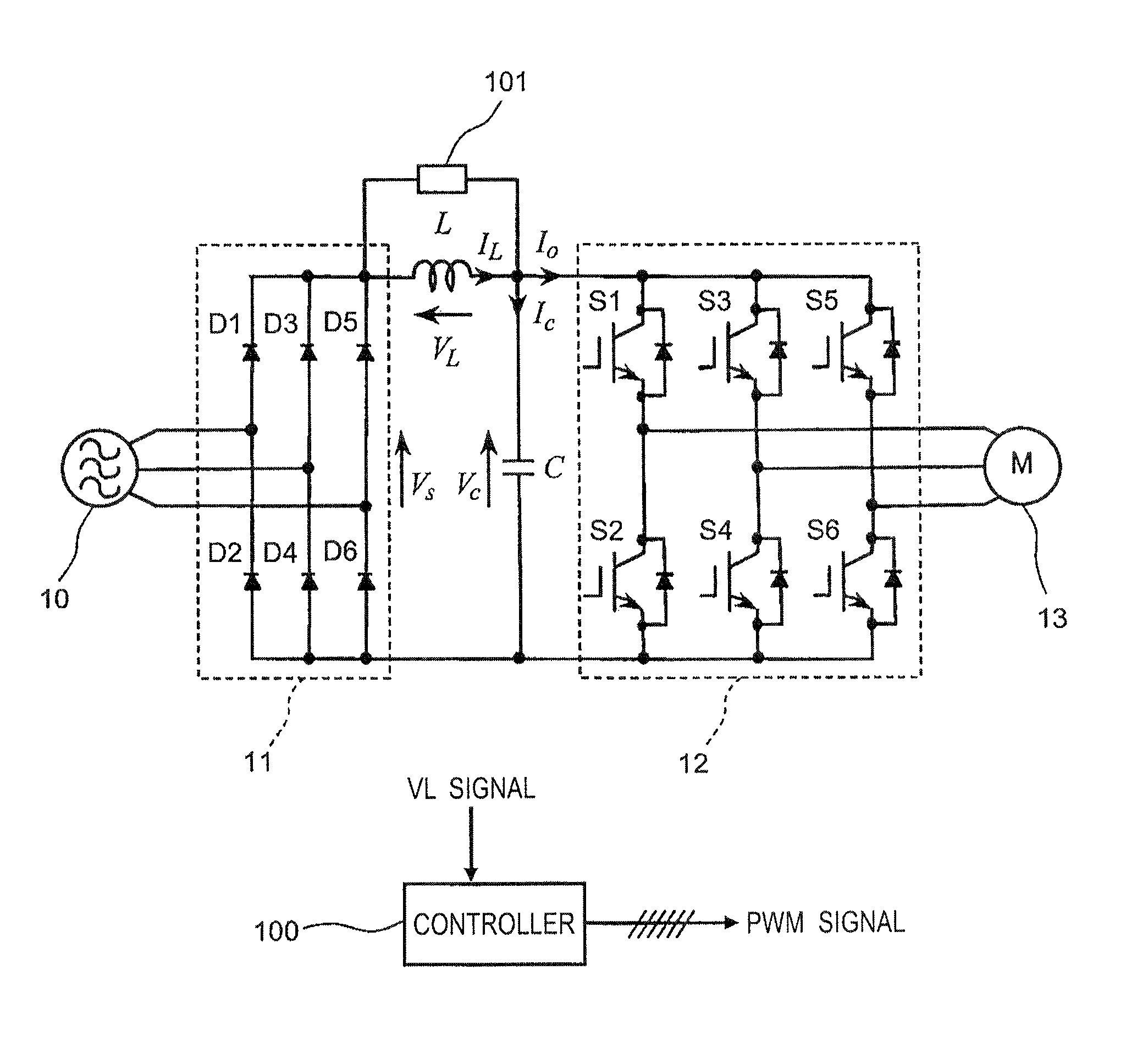
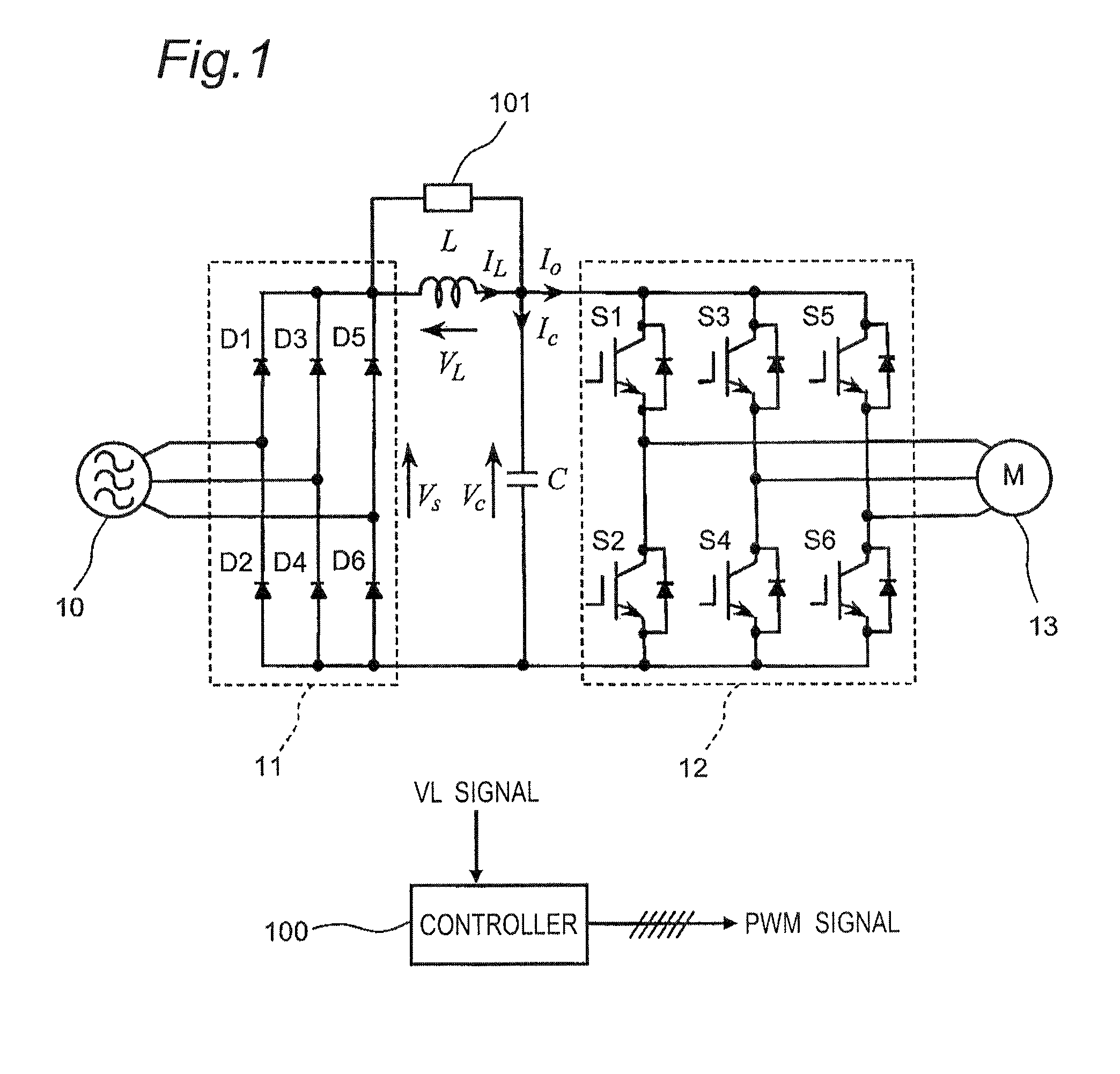
[0106]FIG. 1 shows a constructional view of a power converter according to a first embodiment of the invention. This power converter, as shown in FIG. 1, includes a diode bridge 11 as an example of a rectifier section composed of six diodes D1-D6 composing a three-phase diode bridge circuit, and an inverter section 12 composed of six switching elements S1-S6 composing a three-phase bridge circuit. The power converter also includes a reactor L as an example of an inductance element connected between a positive-pole side output end of the diode bridge 11 and a positive-pole side input end of the inverter section 12, and a capacitor C as an example of a capacitance element connected between input ends of the inverter section 12. The reactor L and the capacitor C constitute an LC filter. The power converter further includes a voltage detector 101 for detecting a voltage across the reactor L, and a controller 100 for outputting a PWM signal to each of the switchin...
second embodiment
[0194](Second Embodiment)
[0195]Next, a power converter according to a second embodiment, which is enabled to improve the stability of the control system of the power converter according to the first embodiment, will be described below.
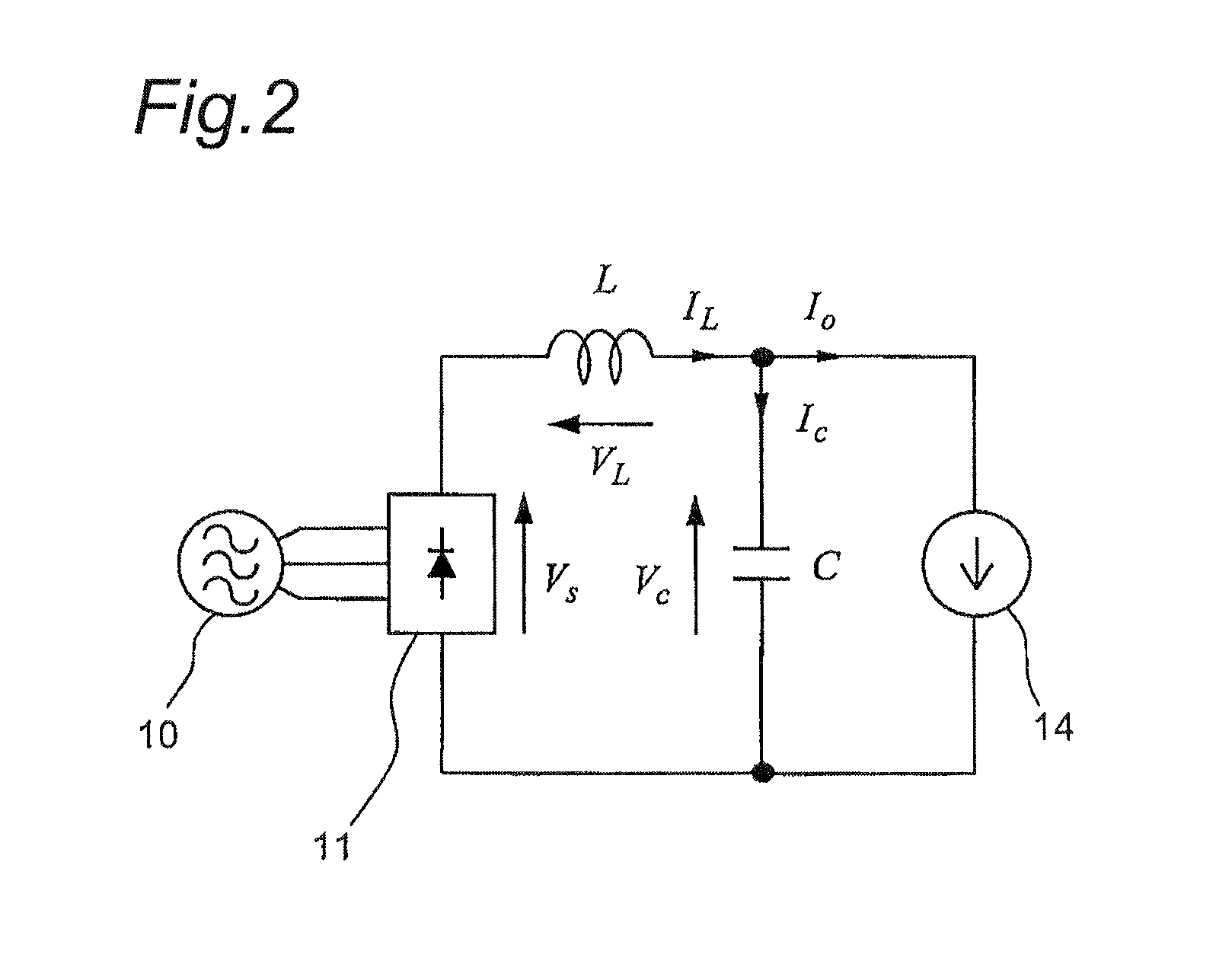
[0196]The power converter of the second embodiment of the invention is similar in construction to the power converter of the first embodiment shown in FIG. 1 except the operation of the controller 100, and therefore FIGS. 1 and 2 are used for reference.
[0197]FIGS. 20(A), 20(B) and 20(C) show block diagrams of the power converter of the second embodiment.
[0198]FIG. 20(A)-20(C), which are block diagrams resulting from determining characteristics of the resonance suppression system with the voltage VL across the reactor L used for resonance suppression, show transfer characteristics of the voltage Vc across the capacitor C (i.e., input voltage of the inverter section 12) versus the DC voltage Vs outputted from the diode bridge 11.
[0199]It can be seen that...
PUM
 Abstract
Description
Claims
Application Information
 - R&D
- Intellectual Property
- Life Sciences
- Materials
- Tech Scout
- Unparalleled Data Quality
- Higher Quality Content
- 60% Fewer Hallucinations
Browse by: Latest US Patents, China's latest patents, Technical Efficacy Thesaurus, Application Domain, Technology Topic, Popular Technical Reports.
© 2025 PatSnap. All rights reserved.Legal|Privacy policy|Modern Slavery Act Transparency Statement|Sitemap|About US| Contact US: help@patsnap.com


