Method and apparatus for repairing concrete

a concrete and method technology, applied in the field of concrete methods and equipment, can solve the problems of concrete damage, high time consumption and labor intensity of methods, and achieve the effects of less expensive, strong anchoring system, and simple implementation

Active Publication Date: 2015-11-24
GARLAND INDS
View PDF32 Cites 5 Cited by
  • Summary
  • Abstract
  • Description
  • Claims
  • Application Information

AI Technical Summary

Benefits of technology

[0010]The present invention is directed to a method and apparatus for strengthening concrete structures, and more particularly directed to a method and apparatus for strengthening and reinforcing preexisting concrete structures. The method for strengthening and reinforcing preexisting concrete structures of the present invention includes the use of a novel composite material that is used to faun an anchor for a reinforcement strip for use with a concrete structure. A portion of the anchor is designed to be connected to the reinforcement strip. The method for strengthening and reinforcing preexisting concrete structures of the present invention is simple to implement, generally less expensive than preexisting anchoring systems, and results in a stronger anchoring system than past anchoring systems.
[0015]In yet another and / or alternative non-limiting aspect of the present invention, the bottom portion of the anchor does not have any cuts or openings. The inclusion, or the forming of one or more cuts or openings in the resin bonded bottom portion of the anchor can reduce the strength of the bottom portion of the anchor. The outer surface of the bottom portion of the anchor can optionally be formed of a second side surface of a fabric layer that includes little or no resin material so as to retain some textured surface that can be used to bond with an adhesive in the cut hole or slot in the concrete structure to thereby secure the bottom portion of the anchor to the concrete structure. However, it can be appreciated that the outer surface of the bottom portion of the anchor can be fully coated with the anchor resin material.
[0023]In still yet another and / or alternative non-limiting aspect of the present invention, the adhesive used to bond the bottom portion of the anchor in the cut slot is generally a different composition from the adhesive used to secure the reinforcement strip to the outer surface of the concrete structure. Generally, the curing time of the adhesive used to secure the bottom portion of the anchor in the cut slot is about 1-10 hours, depending on the ambient temperature. Generally, the curing time of the adhesive used to secure the bottom portion of the anchor is less than the curing time of the adhesive used to bond the reinforcement strip to the outer surface of the concrete structure. This curing time difference is advantageous to create the desired reinforcement structure.
[0029]It is yet another and / or alternative non-limiting object of the present invention to provide a method and apparatus for reinforcing concrete that is relatively simple and time efficient to install.

Problems solved by technology

However, hammering the anchor to join the edges of the reinforcing sheet requires a great deal of time and the anchors or the fitting members generally protrude from the surface of the concrete which is aesthetically displeasing and / or creates other problems such as when facing panels are to be connected to the concrete.
This method can be very time consuming and labor intensive.
Also, the drilling of holes through the concrete can result in damage to the concrete.
However, steel plates are heavy and difficult to install.
The weight of the steel plate can also create weight issues in the building.
As such, the problem the anchors are meant to deal with is to maintain the reinforcement strip and concrete structure together long enough such that the reinforcement strip can reach its maximum capacity.
When a concrete beam or column begins to bend, such bending only accelerates the debonding of the reinforcement strip from the concrete surface, thus resulting in the reinforcement strip peeling off of the concrete surface.
The anchors are not designed to prevent the reinforcement strip from debonding from the concrete.
Although the prior art methods for reinforcing concrete disclosed in the '776 patent and the '840 patent are effective in strengthening the concrete, the anchors fail long before the reinforcement strip can reach its maximum capacity.

Method used


Image

  • Method and apparatus for repairing concrete
  • Method and apparatus for repairing concrete
  • Method and apparatus for repairing concrete

Examples


Embodiment Construction

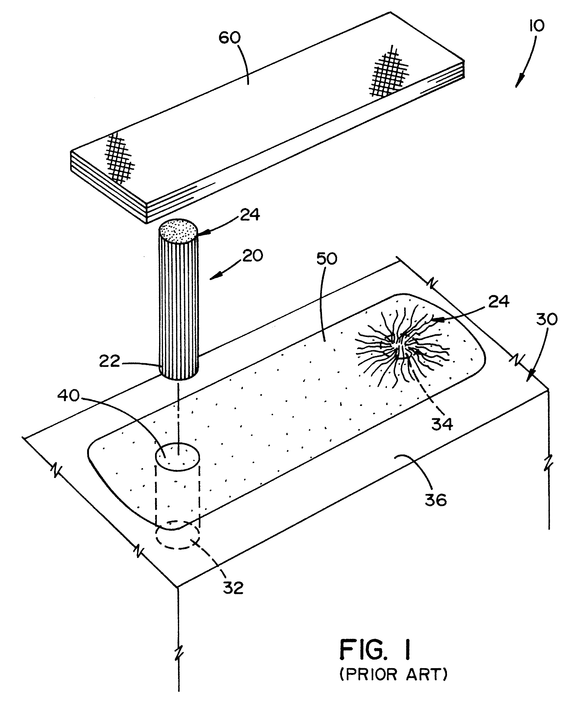
[0046]Referring now to the drawings wherein the showings are for the purpose of illustrating preferred embodiments of the invention only and not for the purpose of limiting same, FIG. 1 illustrates a prior art concrete reinforcement system 10. FIG. 1 illustrates the use of a fiber reinforcement strip, such as a Carbon Fiber Reinforced Plastic (CFRP) sheet, to strengthen a concrete structure. One of the major problems associated with the reinforcing of concrete with fiber reinforced strips is the debonding of the reinforcement strip from the concrete structure before the reinforcement strip has achieved its maximum potential strength in reinforcing the concrete structure. To address this debonding problem, anchors have been used with the fiber reinforcement strip to prevent the debonding of the fiber reinforcement strips from the concrete structure. A common type of anchor that has been used is the Splay anchor. This type of anchor is illustrated in FIG. 1. These types of anchors are...


PUM

PropertyMeasurementUnit
widthaaaaaaaaaa
widthaaaaaaaaaa
widthaaaaaaaaaa

Abstract

An improved anchor for securing a reinforcement strip to a concrete structure.

Description

[0001]The present invention is directed to a method and apparatus for strengthening concrete, more particularly directed to a method and apparatus for reinforcing a concrete structure, and more particularly directed to a method and apparatus for a connector used in reinforcing a concrete structure.BACKGROUND OF THE INVENTION[0002]Concrete is a common material for use in the construction of larger buildings because the concrete is relatively inexpensive and has good compressive strength. Buildings such as multilevel apartment buildings, office buildings and the like are designed to support their own weight plus that of expected inhabitants and furnishings. Concrete materials have excellent vertical compression properties, thus are used in such structures.[0003]Many different techniques have been used to reinforce concrete. One common method for reinforcing concrete includes the use of a reinforcing sheet made of reinforcing fibers, such as carbon fibers, aramid fibers, glass fibers, ...

Claims


Application Information

Patent Timeline
Patent Type & Authority Patents(United States)
IPC IPC(8): E04G23/02E04C5/07E04C5/16
CPCE04G23/0218E04C5/073E04C5/16E04G2023/0251E04G2023/0262
Inventor HEMPHILL, WILLIAM SCOTT
Owner GARLAND INDS
Why Eureka
Try Eureka