
Reactive power balancing current limited power supply for driving floating DC loads

a technology of reactive power balancing and power supply, which is applied in the direction of transmission systems, electric signal transmission systems, semiconductor lamp usage, etc., can solve the problems of deviating from the ideal “resistive” load, unable to work directly with ac power, and requiring dc power for solid-state devices and batteries, etc., to improve the reactive power balance of local premises and/or local grid, improve the power quality of the electrical grid, and improve power supply efficiency

Inactive Publication Date: 2015-11-17
AMBIONCE SYST
View PDF141 Cites 5 Cited by
  • Summary
  • Abstract
  • Description
  • Claims
  • Application Information

AI Technical Summary

Benefits of technology

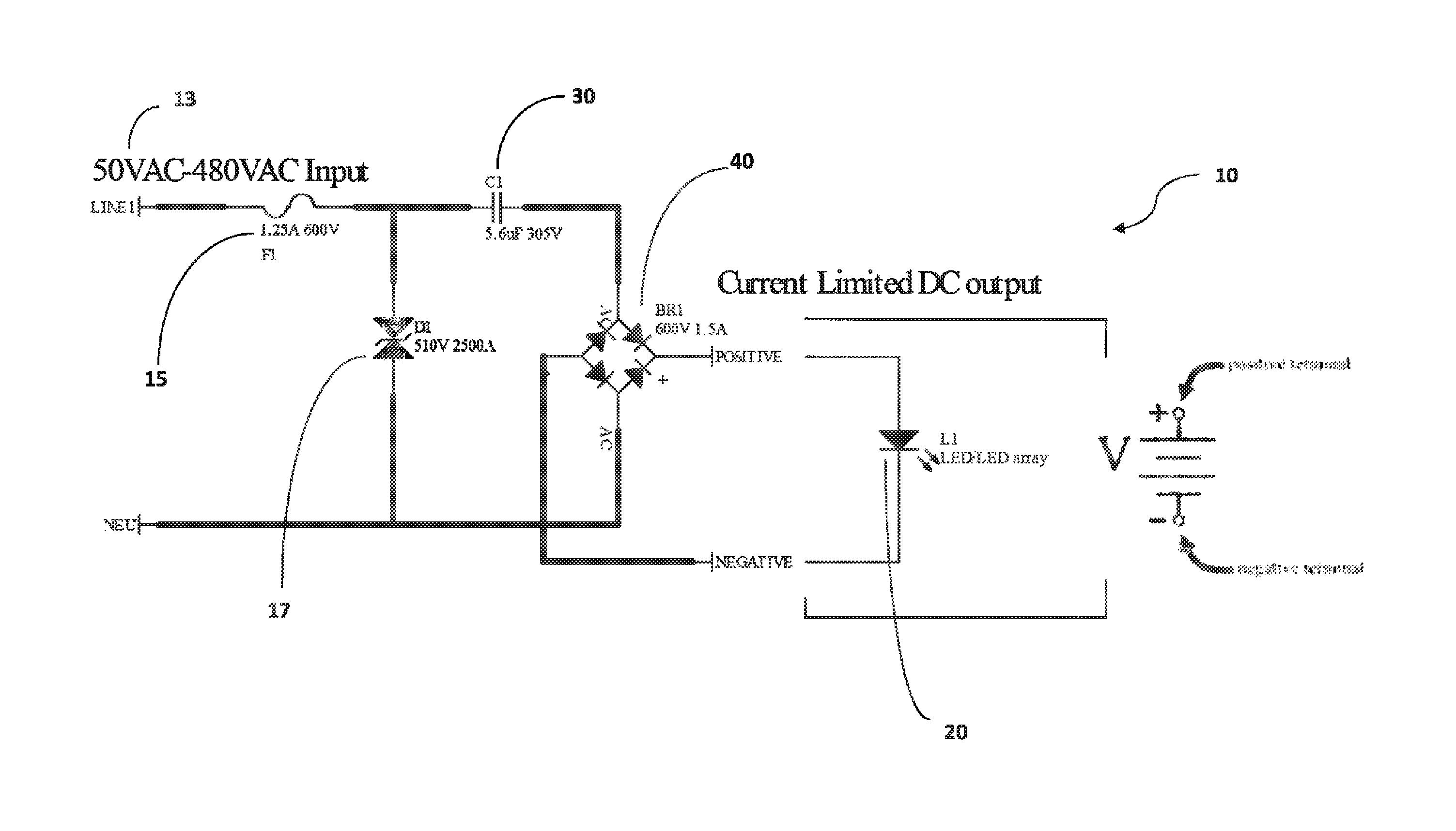
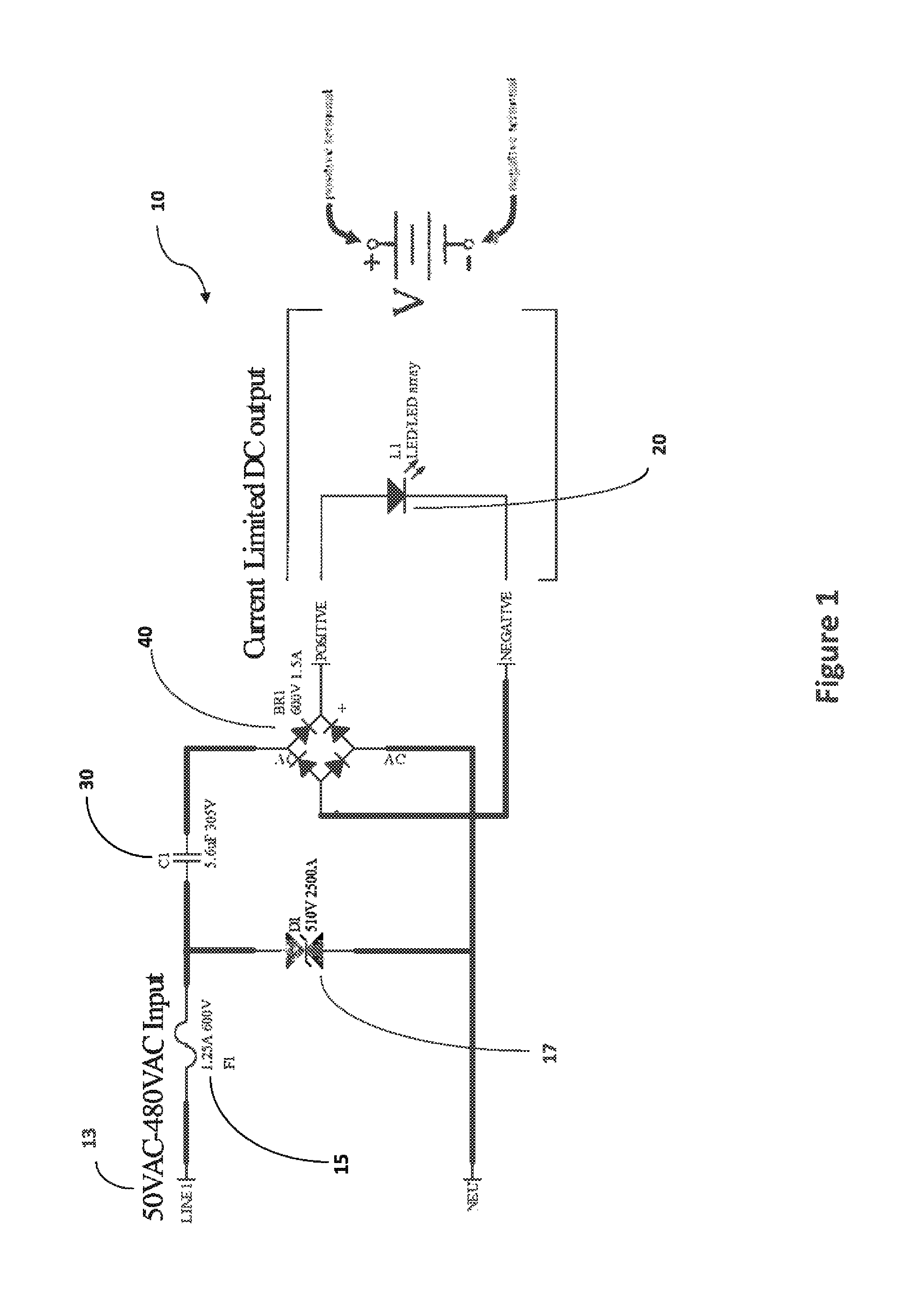
[0032]The present invention is directed to a reactive power balancing current limited power supply (RPBCLPS) for driving floating DC loads, such as for LED lighting, battery charging stations, and other applications which involve converting high voltage AC power to low voltage DC power for loads that require limited current. More in particular, the invention is directed to a power supply which utilizes capacitive reactance to limit the current being supplied to the load, rather than inductance. Accordingly, the present invention provides improved power supply efficiency, limits surge when first powered, improves reactive power balance of the local premises and / or local grid, improves power quality of the electrical grid, and reduces EMI present on the grid.
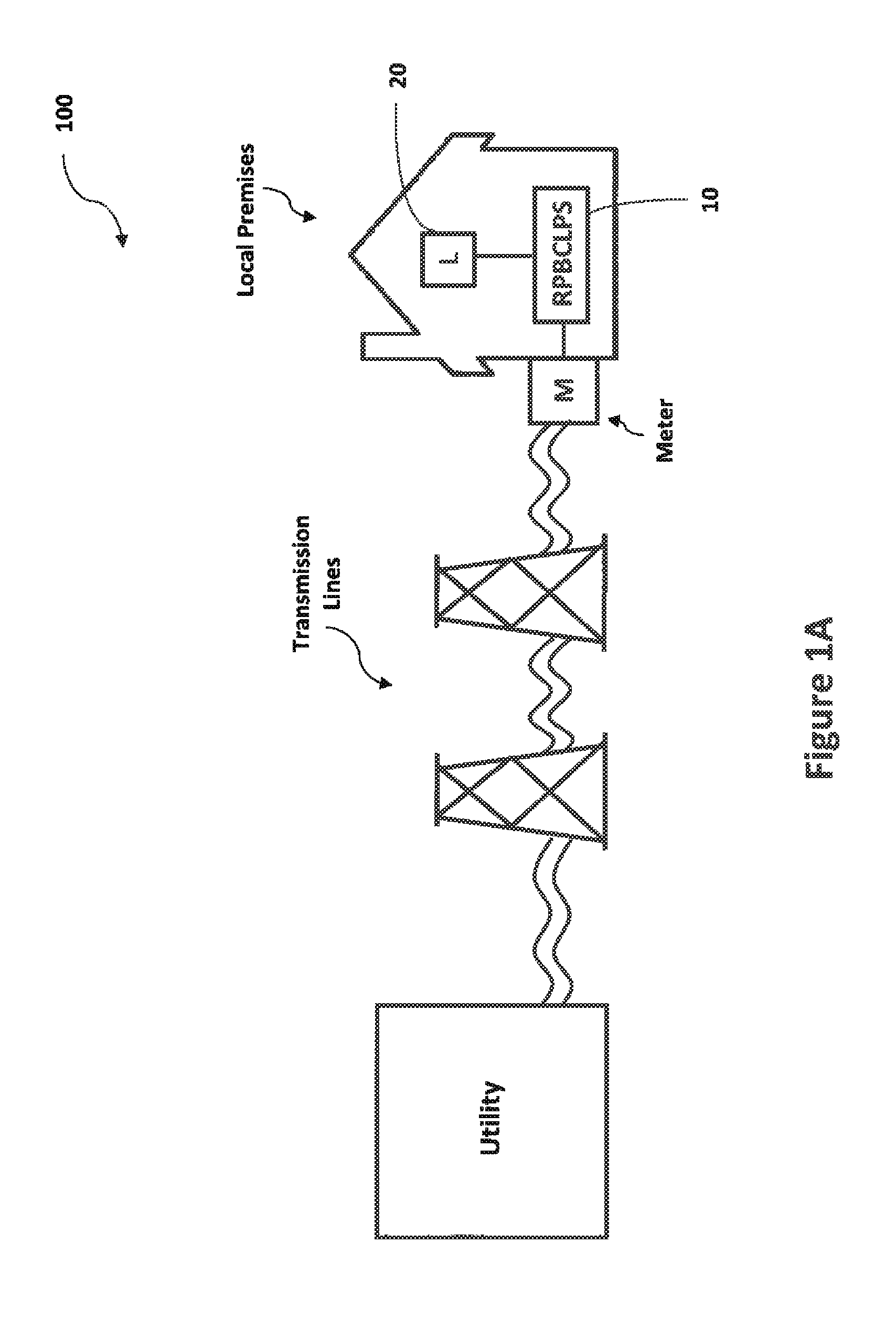
[0035]With regard to system-level implementation, by incorporating light fixtures or other devices that use the inventive power supply of the present invention, the electric utility customer is able to do two things with the same dollar. The first is to remove existing inductive lighting (fluorescent and HID) and other devices from the building or other locale. This reduces the inductive reactive energy required by the building / location. Second, they can implement RPBCLPS-powered LED lighting other devices, thus adding local capacitance to the local / building power grid.
[0037]In another embodiment, battery charging stations positioned around a city will perform the same type of function as noted in the preceding paragraph. Using RPBCLPS based battery chargers will help clean up the power grid and make it more efficient. The chargers will also be light-weight, portable and rugged. On a similar note, utilizing RPBCLPS based golf cart charging stations at golf courses will provide another source of ready capacitance for the grid. Other applications of the present invention include emergency lighting systems, DC motors, and aviation electronics.
[0041]In still other embodiments, the power supply of the present invention can be structured to provide a remote shutdown capability, such as by incorporating a microcontroller or relay switch to facilitate remote shutdown of the load.

Problems solved by technology

With such changes come certain new challenges, particularly in the way devices are powered, which can have various effects on the local premises as well as the broader energy grid.
This presently entails a variety of drawbacks that remain with implementation of current technologies, in addition to the various shortcomings associated with the aforementioned newly emerging technologies.
In light of the foregoing definitions, one problem in the art involves the use of magnetics (inductors or transformers) by typical AC / DC power supplies to reduce voltages to usable levels for solid state components or batteries.
Solid state devices and batteries require DC power and cannot work with AC power directly.
Conducted and radiated EMI create problems by interfering with radio, and other wireless control and communication systems.
This technique deviates from the ideal “resistive” load that power companies prefer to drive.
This creates a problem in that reactive energy must still be delivered to charge the reactive components.
Regarding power supplies, in particular, the inductive nature of the traditional power supply reduces the overall power factor (“PF”) of the building electrical system unless corrected inside the power supply—which adds cost, inefficiency, and complexity to the power supply (therefore, less “green”).
Even though a single power supply can correct its own power factor, it only improves the overall power factor by adding more real power to the system; it does not help balance the inductance and reactance present on the grid.
In other words, while PFCorrected power supplies may not add to the overall reactive energy problem, they do not help it either.
A high PF benefits both the customer and the utility, while a low PF indicates poor utilization of electrical power and adds cost to the delivery of power to the customer which is passed on as higher energy cost.
Thus, low PF results in higher utility costs.
Low PF also results in overheating in wires, circuit boards and motors.
This component of current creates reactive power that does not do useful “work,” but circulates between the generator and the load.
It places a heavier drain on the power source, as well as on the power source's distribution system.
Without the proper power, an electrical device (or load) may malfunction, fail prematurely or not operate at all.
The complexity of the system to move electric energy from the point of production to the point of consumption combined with variations in weather, generation, demand and other factors provide many opportunities for the quality of the supply of electric power to be compromised.

Method used


Image

  • Reactive power balancing current limited power supply for driving floating DC loads
  • Reactive power balancing current limited power supply for driving floating DC loads
  • Reactive power balancing current limited power supply for driving floating DC loads

Examples


Embodiment Construction

[0052]The present invention is directed to a reactive power balancing current limited power supply (RPBCLPS) for driving floating DC loads, such as for LED lighting, battery charging stations, and other applications which involve converting high voltage AC power to low voltage DC power for loads that require limited current. More in particular, the invention is directed to a power supply which utilizes capacitive reactance to limit the current being supplied to the load, rather than inductance. Accordingly, the present invention provides improved power supply efficiency, limits surge when first powered, improves reactive power balance of the local premises and / or local grid, improves power quality of the electrical grid, and reduces EMI present on the grid.

[0053]As schematically represented in the circuit diagram of FIG. 1, one embodiment of the present invention is shown, namely, a capacitance based reactive power balancing current limited power supply (“RPBCLPS”) 10 for driving an...


PUM


Abstract

A capacitance based reactive power balancing current limited power supply (RPBCLPS) for driving floating DC loads utilizes capacitive reactance to limit current being supplied to a load, rather than inductance. A capacitor transfers charge from an AC current input to a DC load. A fuse electrically protects the capacitor from high frequency current harmonics. A diode clamp electrically protects the capacitor from voltage spikes. A rectifier converts the AC current input into DC current for driving the DC load. The reactive power balancing current limited power supply can be incorporated as a key component into reactive power balancing electrical power distribution systems. Such systems can comprise a grid configuration structured to distribute the AC electrical power from a utility source to a plurality of DC loads. Further, the DC loads can be cooperatively located to provide functional distributed capacitance throughout a substantial portion of the grid.

Description

CLAIM OF PRIORITY[0001]The present application is based on and a claim to priority is made under 35 U.S.C. Section 119(e) to provisional patent application currently pending in the U.S. Patent and Trademark Office, having Ser. No. 61 / 792,831 and a filing date of Mar. 15, 2013, the entirety of which is incorporated herein by reference.BACKGROUND OF THE INVENTION[0002]1. Field of the Invention[0003]The present invention is directed to a reactive power balancing current limited power supply (RPBCLPS) for driving floating DC loads, such as for LED lighting, battery charging stations, and other applications. More in particular, the invention is directed to a power supply which utilizes capacitive reactance to limit the current being supplied to the load, rather than inductance. Accordingly, the present invention provides improved power supply efficiency, limits surge when first powered, improves reactive power balance of the local premises and / or local grid, improves power quality of the...

Claims


Application Information

Patent Timeline
Patent Type & Authority Patents(United States)
IPC IPC(8): H02M7/217H05B33/08H02M1/42H05B44/00
CPCH05B33/0809H02M1/4266Y02B20/341Y10T307/406Y02B20/30Y02B70/10H05B45/3725H02M7/05
Inventor STEPPS, DALE B.
Owner AMBIONCE SYST
Learn More