Lighting control system for vehicle lamp

a control system and vehicle lamp technology, applied in the direction of vehicle components, signalling/lighting devices, optical signalling, etc., can solve the problems of complicated system configuration, difficult complicated wiring structure, etc., to reduce the number of harnesses for connecting the light controller and the lamp, simplify the configuration of the system, and facilitate the system construction

Active Publication Date: 2015-11-17
KOITO MFG CO LTD
View PDF11 Cites 4 Cited by
  • Summary
  • Abstract
  • Description
  • Claims
  • Application Information

AI Technical Summary

Benefits of technology

[0011]One of aspects of the present invention is to provide a lighting control system for a vehicle lamp which reduces the number of components, decreases the number of harnesses so as to achieve simplification and reduction in cost of a system configuration.
[0018]According to the present invention, one or two power lines, which are divided to the first lamp lighting circuit of the main lamp and the second lamp lighting circuit of the separate lamp, are connected, the lighting controller is connected to the control circuit of the main lamp by one main lighting control line, the control circuit is connected to the second lamp lighting circuit of the separate lamp by one secondary lighting control line. Thus, the lighting control of the plurality of lamps can be realized. Accordingly, the number of harnesses for connecting the light controller and the each lamp is decreased, simplification of a configuration of the system is improved, and the system can be easily constructed.
[0019]According to the present invention, since the first lamp lighting circuit and the second lamp lighting circuit are configured of a light emitting element drive circuit having the same configuration for emitting each semiconductor light emitting element, each lamp lighting circuit can be configured using the same drive circuit, and the types of components can be reduced.
[0020]According to the present invention, since the modulated lighting signals are output from the control circuit of the main lamp and the second lamp lighting circuit makes the light source of the separate lamp emit light with a different light intensity by the lighting signals, a plurality of lamps using the common light source and the common lamp lighting circuit can be configured, and the number of components can be reduced.
[0021]According to the present invention, since the main lamp and the separate lamp includes a common power line and the lighting controller is configured to control ON and OFF of the common power line, the number of the power lines can be reduced. Moreover, since the main lamp and the lighting controller are connected to each other by a main lighting control line which transmits the lighting control signals, and the main lamp and the separate lamp are connected to each other by a secondary lighting control line which transmits the lighting signals, the number of the lighting control lines can be reduced.
[0022]In addition, since the first lamp lighting circuit and the control circuit are integrally configured as lamp controller, the number of components can be reduced.

Problems solved by technology

Accordingly, the size of the relay box in which four relay switches RL11 to R14 are built-in is increased, the number of harnesses, which configure control lines Lc connecting each of the relay switches RL11 to RL14 to the body ECU 103 or power lines L11 to L14 for connecting each of the relay switches RL11 to RL14 to each of lamps HiL, LoL, CLL, and DRL, is significantly increased, and thus, there is a problem that a wiring structure is complicated.
However, instead of this, electric equipment connectors in the number corresponding to the number of the lamps are needed, and thus, a configuration of the system is complicated.
Moreover, the number of power lines or control lines which connect the control ECU and each lamp is also increased, and thus, it is difficult to decrease the number of harnesses.
However, in a case where the plurality of lamps are configured as an independent lamp, for example, as shown in FIG. 6, in the case where the CLL and DRL are integrated and configured of a lamp (hereinafter, referred to as C / DL) separate from the HL, the lighting control of the separate C / DL cannot be performed by the lamp ECU built in the HL.
Accordingly, although one power line can be configured with respect to the HiL and the LoL configuring the HL, with respect to the C / DL, the power lines are needed to be connected to the CLL and the DRL via relay switches respectively, and as a result, a total of three relay switches and three power lines are needed, and it is difficult to decrease the number of harnesses (see e.g., JP-A-2006-62594).
As described above, in the lighting control system of the related art, there is a problem that the number of the relay switches or the number of the harnesses of the power lines, the control lines, and the like is increased in accordance with the number of the lamps.
Even in a case where the lamp ECU is provided and the lighting is collectively controlled, in order to solve the problems, there is a problem that reduction effects in the number of the relay switches or reduction effects in the number of harnesses cannot be obtained when some lamps are configured as the separate lamps, and there is a problem that simplification or a reduction of cost of the lighting control system is not easily realized.

Method used


Image

  • Lighting control system for vehicle lamp
  • Lighting control system for vehicle lamp
  • Lighting control system for vehicle lamp

Examples


Embodiment Construction

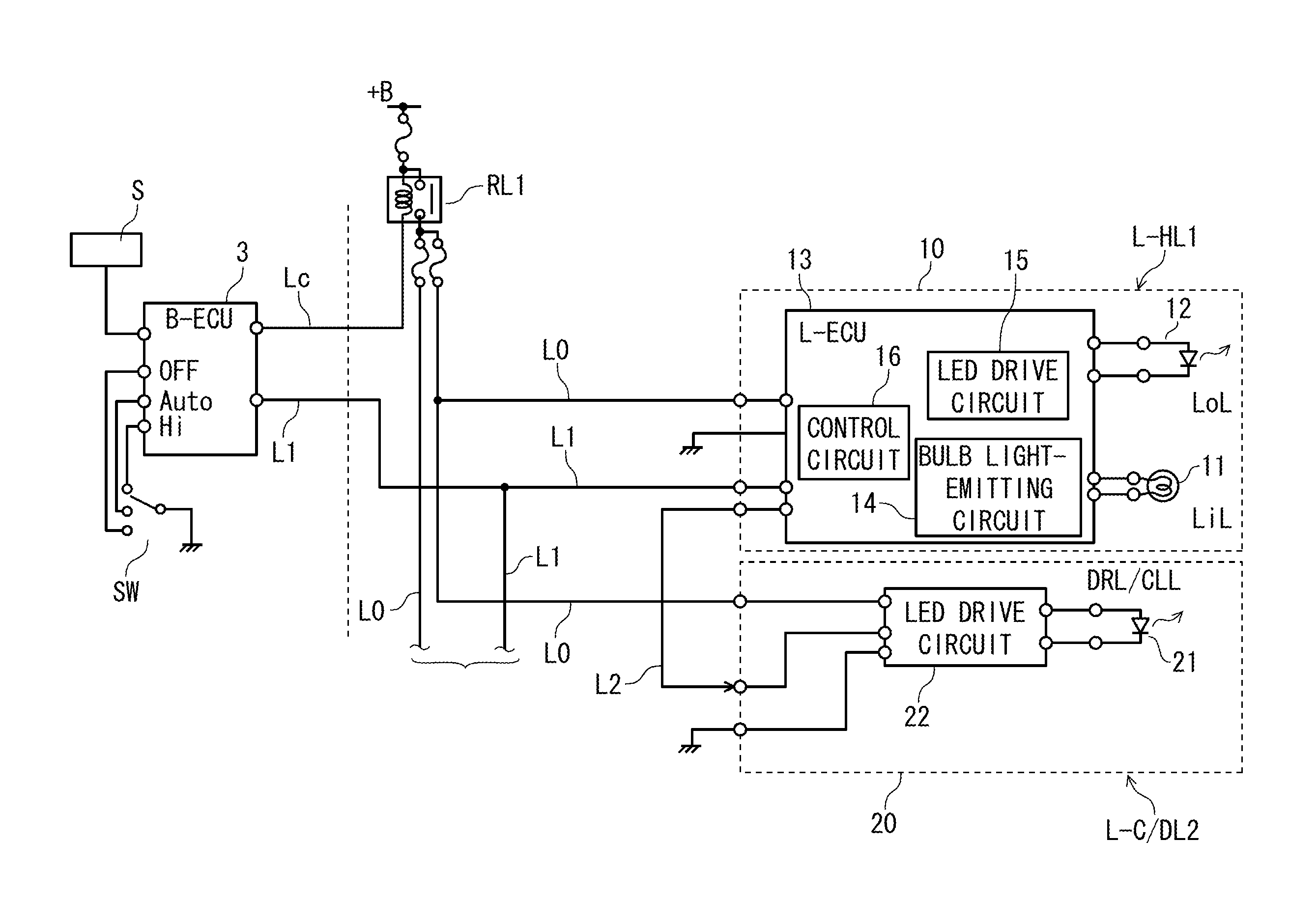
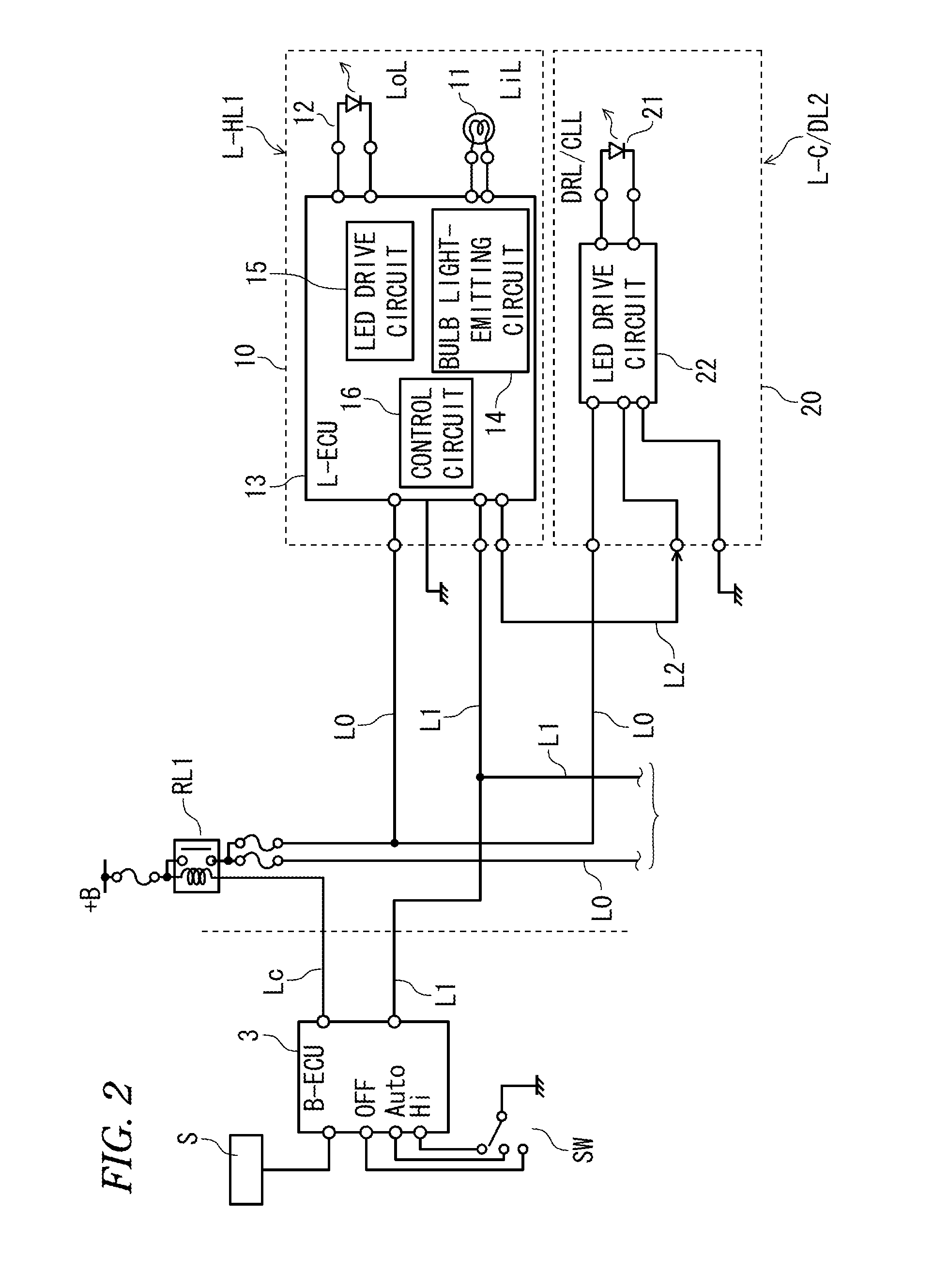
[0029]Next, an embodiment of the present invention will be described with reference to the drawings. FIG. 1 is a schematic perspective view of an automobile CAR mounted with a lighting control system of the present invention. FIG. 2 is a block diagram of the lighting control system. As shown in FIG. 1, a vehicle lamp according to the present invention includes left and right HL1 (head lamp: headlight), that is, an L (left)-HL and an R (right)-HL as a main lamp. Moreover, as a separate lamp, auxiliary left and right lamps 2 (here, referred to as L-C / DL and R-C / DL) are provided in which a CCL (clearance lamp: side marker lamp) and a DDL (daytime running lamp: day run lamp) are integrally mounted. The L-HL and the R-HL are disposed in the left and right sides of a front surface of the automobile CAR respectively, and the L-C / D and the R-C / DL are separated from the R-HL and the L-HL respectively and are disposed in the left and right sides of a front bumper of the automobile CAR respect...


PUM


Abstract

There is provided a lighting control system of a vehicle lamp. The system includes: a plurality of lamps including: a main lamp; and a separate lamp which is separated from the main lamp; and a lighting controller configured to control lighting of the plurality of lamps. The main lamp includes: a first lamp lighting circuit configured to perform a lighting operation of the main lamp; and a control circuit configured to output a lighting signal based on a lighting control signal output from the lighting controller. The separate lamp includes: a second lamp lighting circuit configured to perform a lighting operation of the separate lamp. The first lamp lighting circuit and the second lamp lighting circuit are configured to perform the lighting operations based on the lighting signal output from the control circuit.

Description

CROSS-REFERENCE TO RELATED APPLICATION[0001]This application claims priority from Japanese Patent Application No. 2012-230491, filed on Oct. 18, 2012, the entire contents of which are hereby incorporated by reference.BACKGROUND[0002]1. Technical Field[0003]The present disclosure relates to a lighting control system for controlling lighting on and off and light intensity of a vehicle lamp including a plurality of lamps.[0004]2. Related Art[0005]In general, in addition to a main lamp such as a head lamp (HL), an auxiliary lamp such as a clearance lamp (CLL) or a daytime running lamp (DRL) is provided in an automobile. In recent years, in automobiles, as a lighting control device for the plurality of lamps, a lighting control system which performs a lighting control using a body electronic control unit (ECU) for performing various controls of the automobiles has been suggested. For example, FIG. 6 is a conceptual configuration view of a lighting control system of the HL including the C...

Claims


Application Information

Patent Timeline
Patent Type & Authority Patents(United States)
IPC IPC(8): B60Q1/04B60Q1/28B60Q1/14
CPCB60Q1/04B60Q1/1423B60Q1/28B60Q2400/30
Inventor KUREBAYASHI, TOSHIHIKO
Owner KOITO MFG CO LTD
Why Eureka
Try Eureka