Fuel cell system, control method for the fuel cell system, and electric vehicle equipped with the fuel cell system

a fuel cell and control method technology, applied in the field of fuel cell systems, can solve the problems of fc relay welding or damage, fuel cell voltage overshoot, and large rise rate of fuel cell voltage, and achieve the effect of restricting false determination and impairing durability

Inactive Publication Date: 2015-10-13
TOYOTA JIDOSHA KK
View PDF3 Cites 1 Cited by
  • Summary
  • Abstract
  • Description
  • Claims
  • Application Information

AI Technical Summary

Benefits of technology

[0008]Accordingly, the invention provides a fuel cell system that restrains the false determination regarding electrical leakage without impairing the durability thereof when the fuel cell starts operation, and also provides a control method for the fuel cell system, and an electric vehicle equipped with the fuel cell system.
[0015]The invention achieves an effect of being able to restrain false determination regarding electrical leakage without impairing the durability of the fuel cell at the time of starting the fuel cell.

Problems solved by technology

However, if hydrogen gas and air are supplied at high pressure to a fuel cell when the fuel cell starts operation, it sometimes happen that the rate of rise of the voltage of the fuel cell becomes large so that the voltage of the fuel cell overshoots its upper-limit voltage.
However, there is possibility of the FC relay being welded or damaged if large current flows through the FC relay when the FC relay is closed to connect the fuel cell and the load system.
However, if the voltage of the fuel cell is raised to the open-circuit voltage, the high voltage can affect the durability of the fuel cell.
In such cases, however, the difference in voltage between the electrical system and the fuel cell is likely to be large, giving rise to the possibility that the transitional current occurring at the time of connecting the FC relay may cause an electrical leakage detector to falsely detect electrical leakage, and therefore the control portion may stop the fuel cell system.

Method used


Image

  • Fuel cell system, control method for the fuel cell system, and electric vehicle equipped with the fuel cell system
  • Fuel cell system, control method for the fuel cell system, and electric vehicle equipped with the fuel cell system
  • Fuel cell system, control method for the fuel cell system, and electric vehicle equipped with the fuel cell system

Examples


Embodiment Construction

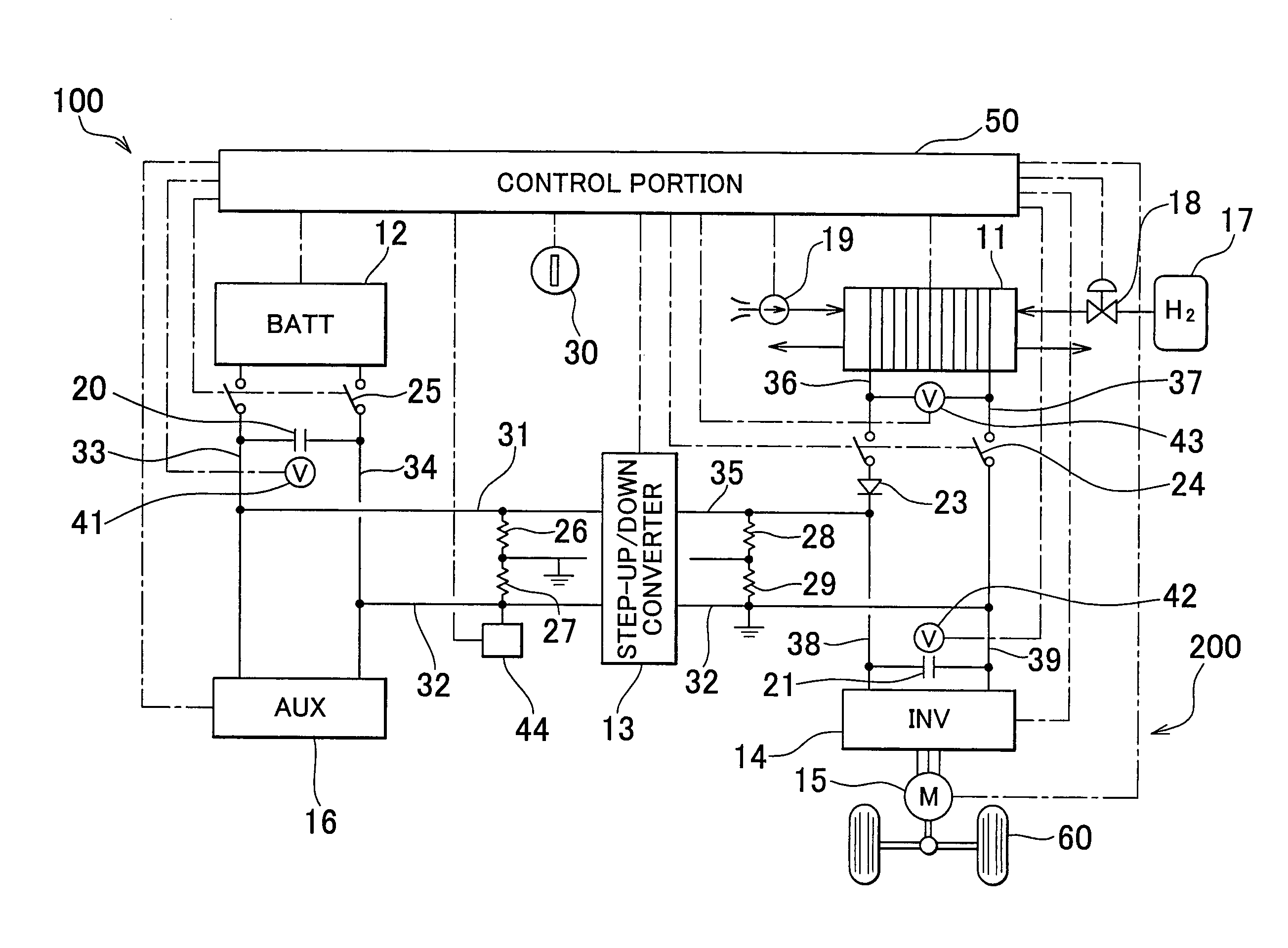
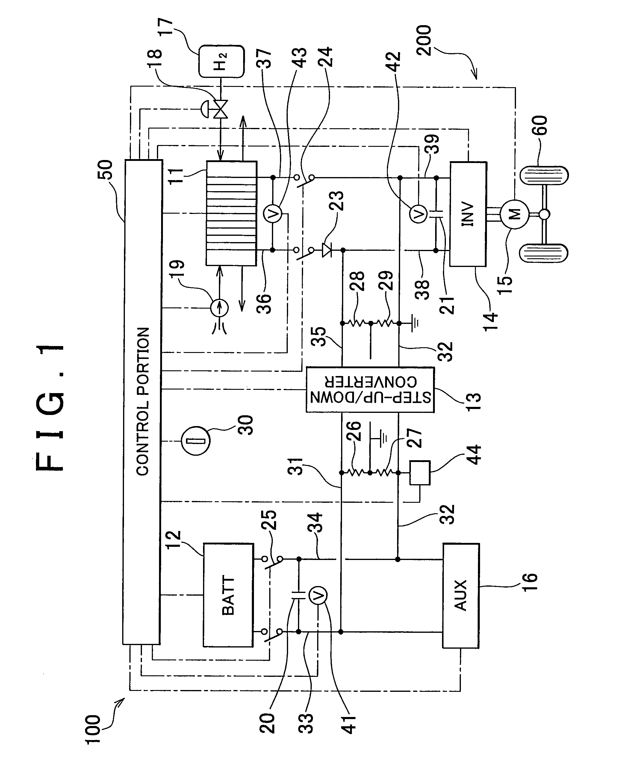
[0022]As shown in FIG. 1, a fuel cell system 100 mounted in an electric vehicle 200 includes a chargeable and dischargeable secondary cell 12, a step-up / down voltage converter 13 that raises or lowers the voltage of the secondary cell 12, an inverter 14 that converts direct-current electric power of the step-up / down voltage converter 13 into alternating-current electric power, and supplies the electric power to a traction motor 15, and a fuel cell 11.

[0023]The secondary cell 12 is constructed of a chargeable and dischargeable lithium-ion battery, or the like. The voltage of the secondary cell 12 in this embodiment is lower than the drive voltage of the traction motor 15. However, the voltage of the secondary cell is not limited so, but may also be a voltage that is equivalent to or higher than the drive voltage of the traction motor. The step-up / down voltage converter 13 includes a plurality of switching elements, and converts a primary-side voltage supplied from the secondary cell ...


PUM

PropertyMeasurementUnit
voltageaaaaaaaaaa
open-circuit voltageaaaaaaaaaa
electrical leakage determinationaaaaaaaaaa

Abstract

A fuel cell system includes: a secondary cell; a voltage converter provided between the secondary cell and a load; a fuel cell; an FC relay that turns on and off electrical connection between the fuel cell and the shared electrical path; an electrical leakage detector that detects electrical leakage in an electrical system; and a control portion that performs determination regarding electrical leakage. The control portion has: start means for starting the fuel cell by raising voltage of the fuel cell from a starting voltage to an operation voltage that is lower than an open-circuit voltage; and electrical leakage determination means for performing the determination regarding electrical leakage after a predetermined time elapses, when the FC relay is closed while a voltage difference between the voltage of the fuel cell and voltage supplied from the voltage converter to the load is greater than a predetermined threshold value.

Description

FIELD OF THE INVENTION[0001]The invention relates to fuel cell system, a control method for the fuel cell system, and a control that is performed on an electric vehicle equipped with the fuel cell system, at the time of starting the electric vehicle.BACKGROUND OF THE INVENTION[0002]Practical application of a fuel cell that supplies hydrogen as a fuel gas to a fuel electrode, and that supplies air as an oxidant gas to an oxidant electrode, and that generates electricity through an electrochemical reaction between hydrogen and oxygen in the air while producing water on an oxidant electrode is now being considered.[0003]In such a fuel cell, if at the time of start of operation, the pressure of hydrogen supplied to the fuel electrode and the pressure of air supplied to the oxidant electrode are about equal to the respective pressures occurring during ordinary operation, it sometimes happens that hydrogen gas and air are unevenly distributed in the fuel electrode and the oxidant electrod...

Claims


Application Information

Patent Timeline
Patent Type & Authority Patents(United States)
IPC IPC(8): H01M8/04
CPCH01M8/04559H01M8/04223H01M8/04664H01M8/04679Y10T307/50H01M2250/20Y02E60/50Y02T90/32H01M8/04955H01M8/04225H01M8/04302Y02T90/40H01M8/04228
Inventor YOSHIDA, MICHIOMATSUMOTO, TADAICHIIMAI, ATSUSHIOGAWA, TOMOYA
Owner TOYOTA JIDOSHA KK
Why Eureka
Try Eureka