End plate for vehicle

a technology for end plates and vehicles, applied in the direction of machines/engines, transportation and packaging, jet propulsion mounting, etc., can solve the problems of affecting the durability of the clutch or the torque converter in the housing, and achieve the effect of facilitating the assembly of the lower end plate to the housing

Active Publication Date: 2020-03-03
TOYOTA JIDOSHA KK
View PDF13 Cites 0 Cited by
  • Summary
  • Abstract
  • Description
  • Claims
  • Application Information

AI Technical Summary

Benefits of technology

[0005]Incidentally, in the vehicle of the type as described above, for example, for avoidance of interference with bolts fixing an oil pan to the engine, avoidance of interference between the upper end plate and the lower end plate, or the like when mounting the end plate on the vehicle, a gap is provided between a lower end edge of the upper end plate and a upper end edge of the lower end plate. For this reason, there is a possibility that sand, muddy water, or foreign matter may enter a housing that accommodates a clutch or a torque converter and impair the durability of the clutch or the torque converter in the housing.
[0006]The disclosure provides an end plate for a vehicle, in which in a vehicle having a gap between an upper end plate and a lower end plate, it is possible to suitably suppress infiltration of foreign matter into a housing through the gap between the upper end plate and the lower end plate.

Problems solved by technology

For this reason, there is a possibility that sand, muddy water, or foreign matter may enter a housing that accommodates a clutch or a torque converter and impair the durability of the clutch or the torque converter in the housing.

Method used


Image

  • End plate for vehicle
  • End plate for vehicle
  • End plate for vehicle

Examples


example 1

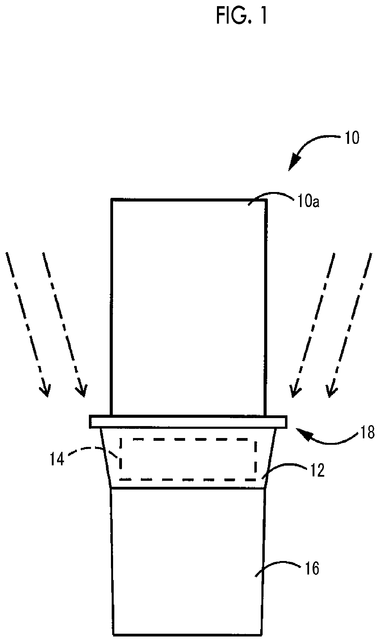
[0037]In FIG. 1, a vehicle is provided with an engine 10, a housing 12 that accommodates a clutch 14 that connects and disconnects the power from the engine 10, a transmission case 16 that accommodates a transmission that shifts the power transmitted through the clutch 14 and transmits the power to the rear wheels, and an end plate 18 of the engine 10, the end plate 18 being provided between the engine 10 and the housing 12. In Example 1, the clutch 14 that is accommodated in the housing 12 is a wet type single plate type, and the transmission that is accommodated in the transmission case 16 is a parallel shaft type constant meshing type manual transmission. However, for example, a configuration may be adopted in which a torque converter is accommodated in the housing 12 and an automatic transmission is accommodated in the transmission case 16.

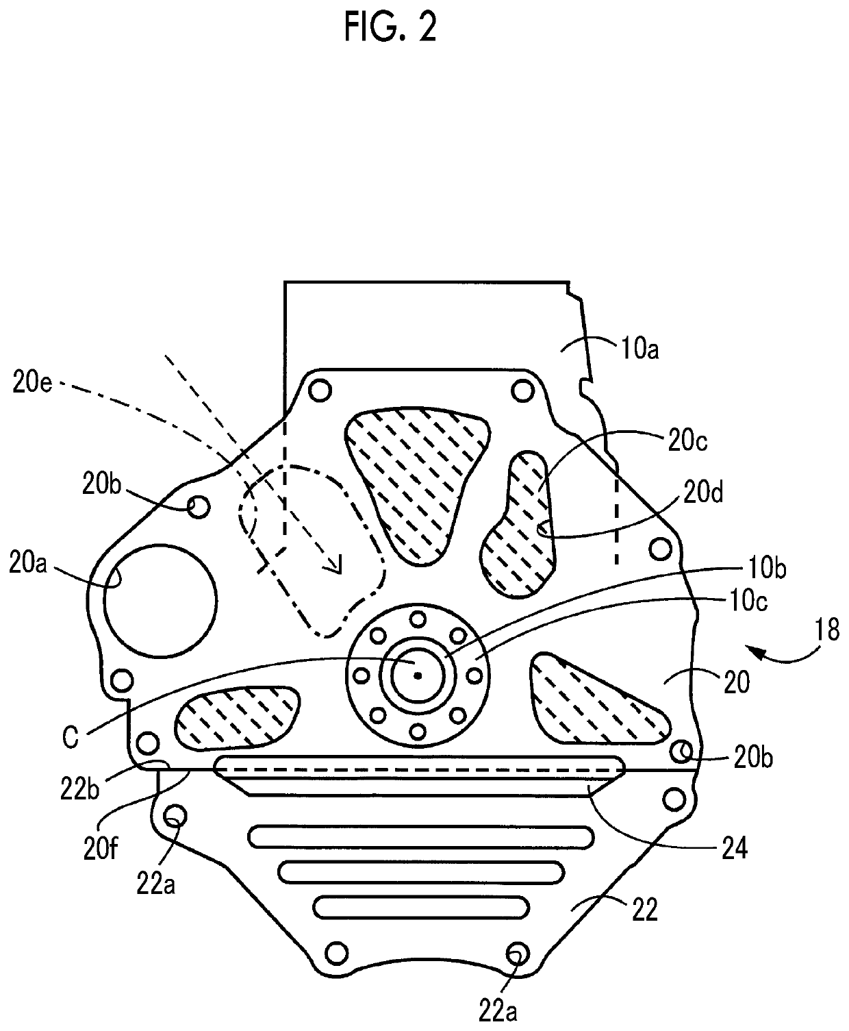
[0038]In FIG. 2, a shaft end of a crankshaft 10b of the engine 10, which rotates around a rotation axis C, penetrates the end plate 18. A fla...

example 2

[0058]FIG. 11 is a schematic diagram showing the shape of the cover 24 of Example 2 of the disclosure, which is applied to the vehicle of FIG. 1. The first flat surface 44a of the cover 24 of Example 2 is further provided with an inclination that increases toward the central portion from both ends in the longitudinal direction of the first flat surface 44a, that is, in the width direction of the lower end plate 22, in addition to the above-described inclination that is directed downward as the first flat surface 44a is directed toward the engine 10 side. According to Example 2, as shown by a one-dot chain line in FIG. 11, in a case where traveling wind that is directed toward the middle side from both the outer sides enters between the engine block 10a and the end plate 18, foreign matter is further restrained from staying on the first flat surface 44a by the traveling wind.

example 3

[0059]FIG. 12 is a schematic diagram showing a vehicle, that is, an FF vehicle, to which the cover 24 of an end plate for a vehicle of Example 3 of the disclosure is applied. In Example 3, as shown by a one-dot chain line, traveling wind that is directed toward the middle side from the outside on one side, which is the front of the vehicle, enters between the engine block 10a and the end plate 18.

[0060]FIG. 13 is a schematic diagram showing the shape of the cover 24 of Example 3, which is applied to the vehicle of FIG. 12. The first flat surface 44a of the cover 24 of Example 3 is further provided with an inclination that increases toward the other end from one end on the windward side and steeply decreases toward the other end portion in the longitudinal direction of the first flat surface 44a, that is, in the width direction of the lower end plate 22, in addition to the above-described inclination that is directed downward as the first flat surface 44a is directed toward the engin...


PUM


Abstract

An end plate for a vehicle includes an upper end plate, a lower end plate, and a cover that covers a gap between a lower end edge of the upper end plate and an upper end edge of the lower end plate. The vehicle includes an engine and a housing. The engine is fastened to the housing through the end plate. A first stepped portion having a pair of a first flat surface and a second flat surface intersecting with the first flat surface is provided on the engine side of the cover. The first flat surface is inclined downward with respect to a horizontal plane as the first flat surface is directed toward the engine side.

Description

INCORPORATION BY REFERENCE[0001]The disclosure of Japanese Patent Application No. 2017-163786 filed on Aug. 28, 2017 including the specification, drawings and abstract is incorporated herein by reference in its entirety.BACKGROUND1. Technical Field[0002]The disclosure relates to an end plate for a vehicle.2. Description of Related Art[0003]For example, as shown in Japanese Unexamined Patent Application Publication No. 2006-002743 (JP 2006-002743 A), there is a case where an end plate is interposed between an engine and a housing of a vehicle. There is a case where the end plate is composed of an upper end plate and a lower end plate that are vertically divided, for shared use of parts, improvement in assembling property, or the like, for example.[0004]In an assembly process in a vehicle of the type as described above, a state where an engine block and the housing are fastened to each other in advance through the upper end plate is created. In the state described above, a lower end p...

Claims


Application Information

Patent Timeline
Patent Type & Authority Patents(United States)
IPC IPC(8): F02F7/00B60K23/02B60K17/02B60K7/00B60K25/02F02B67/00B60K5/04F02B67/04B60K5/12
CPCB60K23/02F02F7/0073F02B67/00B60K25/02B60K5/1216B60K7/00B60K5/04F02B67/04B60K17/02F02F7/0068B62D25/082B62D25/105B62D25/12F02F7/0065F02B77/00F16H57/00
Inventor TAKENAKA, TETSUHIRO
Owner TOYOTA JIDOSHA KK
Why Eureka
Try Eureka