
Multi-valve fuel injection system and injection method

a fuel injection system and multi-valve technology, applied in the direction of electric control, speed sensing governor, machine/engine, etc., can solve the problems of slow cycle response speed, speed fluctuation, and inability to get the maximum fuel injection, so as to improve the response feature of the system, improve the starting characteristic of the liquid fuel engine, and improve the reliability of the system

Inactive Publication Date: 2015-10-13
LIU FUSHUI
View PDF7 Cites 2 Cited by
  • Summary
  • Abstract
  • Description
  • Claims
  • Application Information

AI Technical Summary

Benefits of technology

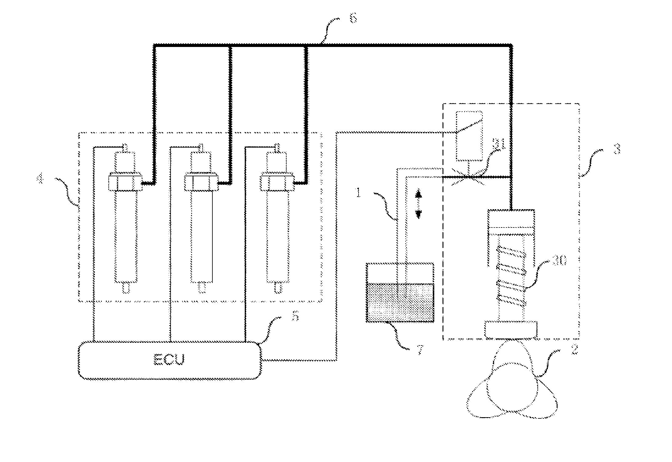
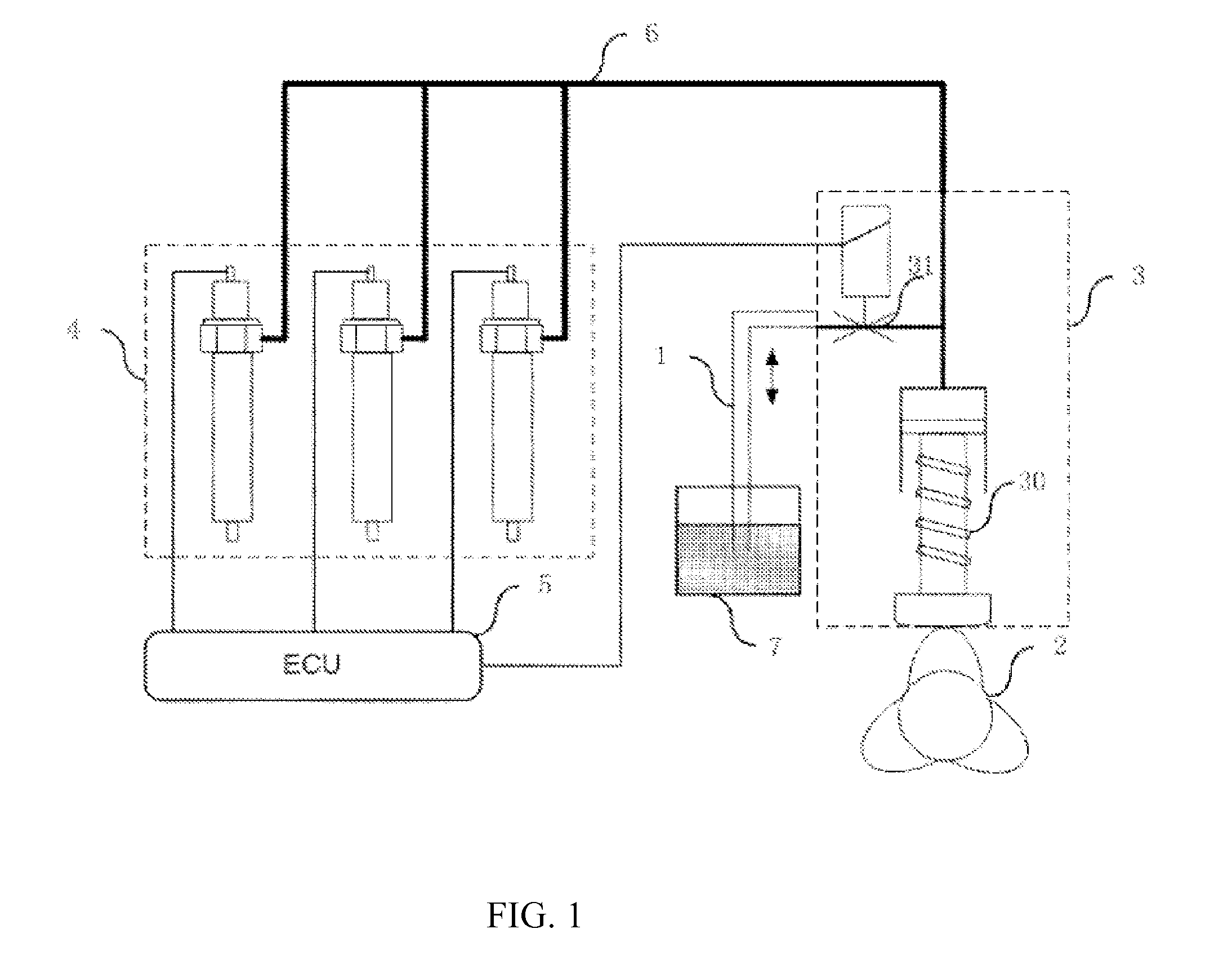
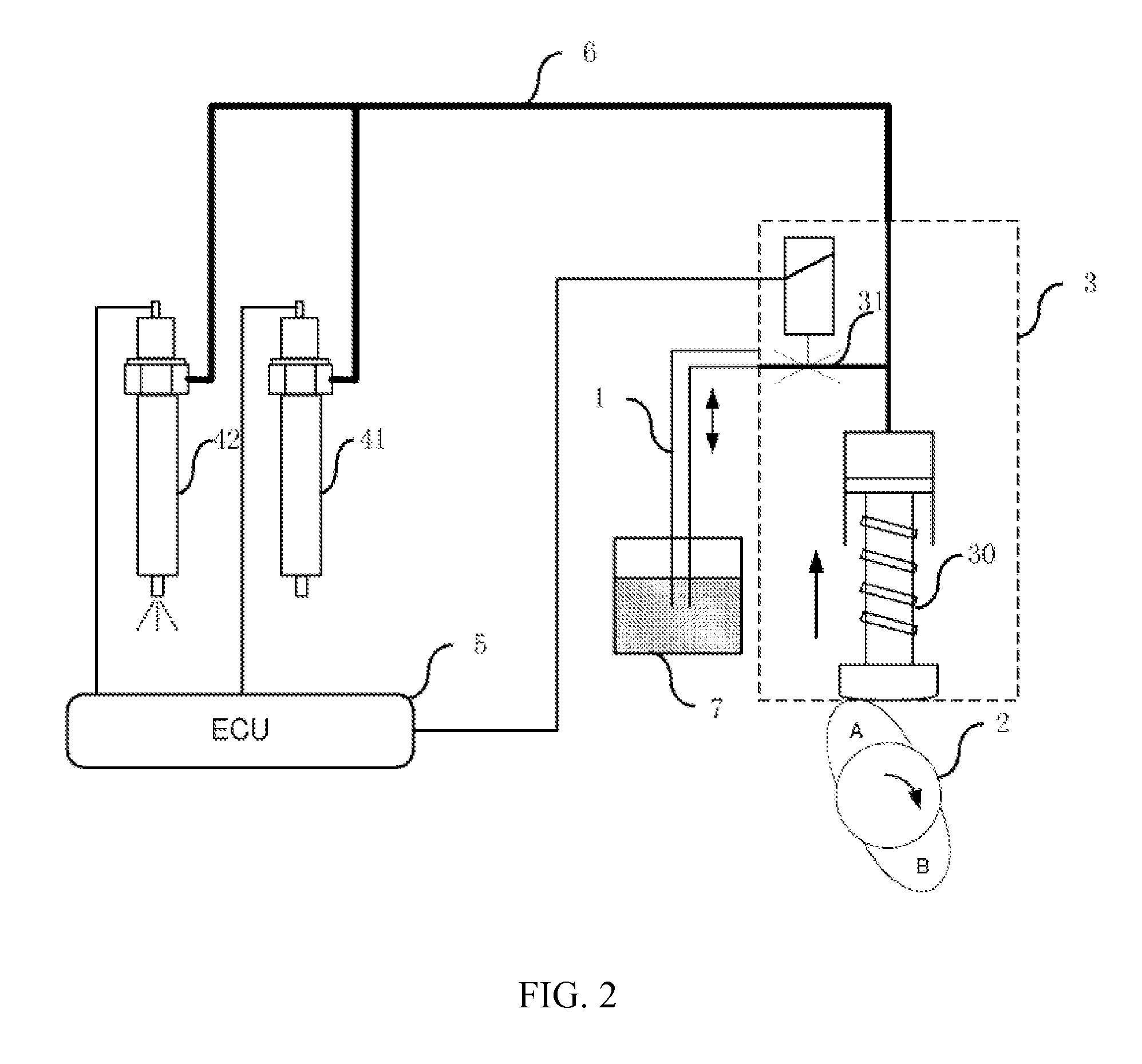
The present invention has the following advantages: replacing the common rail cavity with a high pressure fuel injection pipe improves the response of the system and synchronizes pressure between the electronic unit pump and fuel injector. The high pressure fuel injection pipe generates only momentary high pressure, improving reliability. The system can quickly adjust fuel supply to match vehicle acceleration needs. The solenoid valves are controlled by electronic control units, adjusting operation timing to generate high pressure at low speeds, improving starting characteristics and reducing emissions. In high-load and speed conditions, the system can achieve large fuel injection in a short time, optimizing combustion process. The use of a single electronic unit pump for multiple cylinders reduces system cost.

Problems solved by technology

Large fuel injection means to require large fuel injector nozzle area.
Under the condition of small fuel injection quantity or idling, the large fuel injector nozzle can cause relatively large fuel injection error which may lead to speed fluctuation.
However, if we accurately control the fuel injection quantity at the low speed, we will not get the maximum fuel injection.
As for the mainstream oil supply system it is a challenge to accurately control the large scope of fuel injection quantity and improve the cycle responding characteristics of the fuel injection system.
But the larger volume of the common rail cavity leads to slower cycle response speed that is unable to regulate injection starting pressure in cycles.
But the disadvantages are also obvious: the injection pressure and fuel injection law can not be adjusted, the injection pressure relates with cam speed which cannot match the injection characteristic for high speed and low speed simultaneously.
It can be concluded that neither high pressure common rail fuel supply system nor electronic unit pump can meet the large fuel injection scope of the highly-intensified diesel engine and high requirements for the cycle response characteristic.

Method used


Image

  • Multi-valve fuel injection system and injection method
  • Multi-valve fuel injection system and injection method
  • Multi-valve fuel injection system and injection method

Examples


Embodiment Construction

[0034]The following drawings describe the invention in details.

[0035]The drawings display embodiment of the invention, in which the identical and similar signs represent the identical and similar components or components possess the identical and similar functions. The following description of the preferred embodiments is merely exemplary in nature and is in no way intended to limit the invention, its application, or uses.

[0036]The following section provides many different embodiments and examples which describe the different structures of the present invention. In order to simplify the publicity of the invention, the following section describes components and settings of a specific example. In fact, they are only exemplary and their aims are not to limit the invention. Besides, the present disclosure can repeat the reference FIGs and / or letters in different examples. These repetitions are for aims of simplifying and clearing, and they don't express the relationship between embodime...


PUM


Abstract

A multi-valve fuel injection system comprising an electronic unit pump for outputting high pressure fuel; a low pressure fuel pipe for inputting fuel into the plunger cavity of the electronic unit pump; a fuel supply cam for propelling the movement of the plunger of the electronic unit pump to produce high pressure fuel; at least two electronically controlled fuel injectors for injecting fuel; high pressure fuel injection pipe connecting the electronic unit pump and the electronically controlled fuel injectors for transporting the high pressure fuel outputted form the electronic unit pump to the electronically controlled fuel injectors, respectively, for controlling the electronic unit pump and the opening and closing of solenoid valves in the fuel injectors. The fuel injection system can achieve large range fuel injection and high circulating response. Also disclosed is a fuel injection method for the multi-valve fuel injection system.

Description

CROSS-REFERENCE TO RELATED APPLICATION[0001]This application is a U.S. National Phase Application of PCT International Application No. PCT / CN2011 / 082347 filed on Nov. 17, 2011, which claims priority to Chinese Patent Application No. 201110344234.4, filed on Nov. 3, 2011, the contents of each of which are incorporated herein by reference in their entirety for all purposes.FIELD OF THE INVENTION[0002]The present invention relates to fuel injection system. In detail, it is to an electronically controlled high pressure fuel supply system and a method characterized by ideal fuel supply performance with full range of operating condition.BACKGROUND OF THE INVENTION[0003]With the development of the liquid fuel engine technology, high power density is greatly needed. The higher efficiency of cylinder combustion process can enhance the engine power, wherein the most important factor is to optimize the fuel injection process.[0004]Taking diesel engine as an example, with the enhancement of the...

Claims


Application Information

Patent Timeline
Patent Type & Authority Patents(United States)
IPC IPC(8): F02D31/00F02D41/40F02M63/02F02M59/10F02M59/02F02M59/36F02D41/38F02M47/02
CPCF02M59/366F02D41/3845F02D41/401F02D41/402F02D41/406F02M59/102F02M63/02F02M59/025Y10T137/86027F02M47/027Y02T10/44Y10T137/0318Y02T10/40
Inventor LIU, FUSHUI
Owner LIU FUSHUI
Learn More