Eureka AIR delivers breakthrough ideas for toughest innovation challenges, trusted by R&D personnel around the world.

Panel forming

a technology of forming panels and forming sheets, which is applied in the direction of building components, floor coverings, domestic articles, etc., can solve the problems of increasing the price of wood fibres and thermosetting resins, limiting further cost savings, and predicting major increases

Active Publication Date: 2015-09-22
CERALOC INNOVATION AB
View PDF187 Cites 41 Cited by
  • Summary
  • Abstract
  • Description
  • Claims
  • Application Information

AI Technical Summary

Benefits of technology

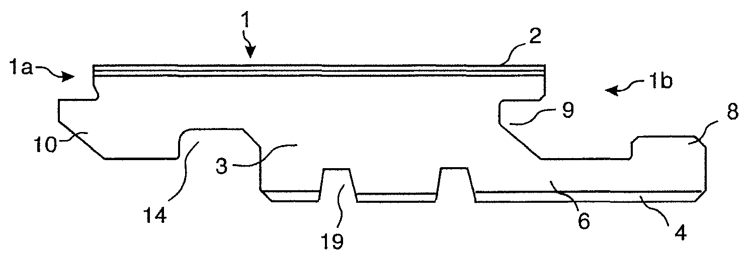
[0031]An objective of embodiments of the present invention is to provide laminated panels comprising thermosetting resins and a method to produce such panels with the aim to reduce the weight and material content of such panels, especially floor panels, and to combine such cost saving and material reducing methods with a high quality locking systems and a core that provides sufficient stability which is needed in the pressing operation and when the floor is used. A further objective is to provide solid wood floors with reduced weight and material content and increased stability.
[0053]The core grooves are used to create wood fibre material that may be used in a second step to form the upper or lower layers of the floor panel. The material that is removed from the core when forming the core grooves, reduces the weight of the panel in spite of the fact that the original panel thickness is maintained and that a panel which is thicker than the original core may be formed by using the chips from the forming of the core grooves. The whole floor panel including the upper and lower layers may be formed by materials comprising the material from the core.

Problems solved by technology

The prices for wood fibres and thermosetting resins are increasing and major increases are expected in the future due to shortage and the possibility to use wood fibres for energy production.
Further cost savings are limited by minimum quality requirements related to the floor panel and the geometry of locking system.
The problem with the present laminate and WFF floors is that they must have a high density core such as HDF that is needed for the stability, impact resistance and the strength which is needed to resist the heat and pressure from the pressing operation.
Another problem is that the panels must have a minimum thickness and a core with high shear strength in order to allow the forming of a locking system with sufficient strength and geometry that allows easy installation.

Method used


Image

  • Panel forming
  • Panel forming
  • Panel forming

Examples


first embodiment

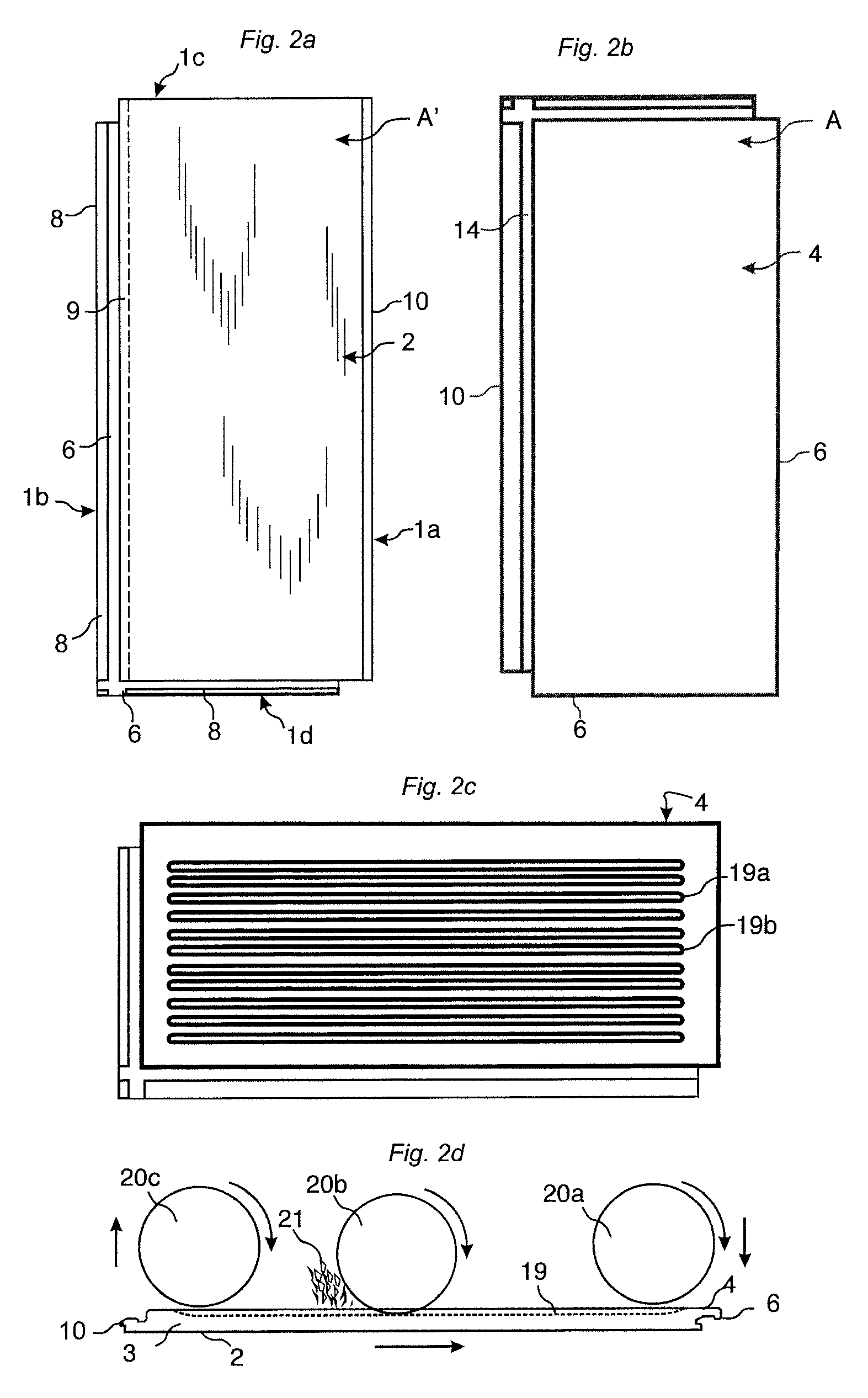
[0073]floorboards provided with a mechanical locking system according to the invention is shown in FIGS. 2a-2d. The floor panel comprises a locking system on long 1a, 1b and short 1c, 1d edges. FIG. 2a shows the front side with the surface layer 2 and FIG. 2b shows the rear side with the backing layer 4. The area of the surface layer A′ is essentially the same as the area A of the backing layer 4. FIG. 2c shows that essentially vertical core grooves 19a, 19b, with an opening toward the rear side or the panel, may be formed on the rear side in the backing layer 4 and into the core 3 that may be a wood based board such as for example HDF, chipboard or plywood. The core may also comprise plastic material. Such forming may be made with rotating saw blades 20a as shown in FIG. 2d. Carving may also be used. The panels are generally machined with the surface layer 2 pointing downwards. The jumping saw blade is displaced towards the panel 20a from above, or below if the surface layer 2 is p...

embodiment 1

[0105]2. The building panels , wherein the backing layer (4) comprises at least three core grooves (19) spaced horizontally and inwardly from the locking system at one pair of opposite edges.

[0106]3. The building panels as in embodiments 1 or 2, wherein the area (A) of the backing layer is less than 80% of the area of the surface layer (A′).

[0107]4. The building panels as in any one of the embodiments 1-3, wherein the entire parts of at least one core groove (19) is arranged inside the vertical plane VP at all edges.

[0108]5. The building panels as in any one of the preceding embodiments, wherein the building panels are rectangular with long edges (1a, 1b) and short edges (1c, 1d) and wherein the core grooves (19) are essentially parallel with the long edges.

[0109]6. The building panels as in any one of the preceding embodiments, wherein the core groove depth (GD) is at least 0.3 times the floor thickness (T).

[0110]7. The building panels as in any one of the preceding embodiments, wh...

embodiment 9

[0119]10. The method wherein the mix is scattered on the lower side of the core.

[0120]11. The method as in embodiment 9 or 10, wherein the mix is scattered on the upper and lower side of the core (3).

[0121]12. The method as in any one of the embodiments 9-11, wherein the core is HDF.

[0122]13. The method as in any one of the embodiments 9-12, wherein the core grooves are formed prior to the forming of the locking system at long or short edges of the floor panels.

[0123]14. The method as in any one of the embodiments 9-13, wherein the core grooves are formed by a jumping tool comprising several rotating saw blades or a carving tool.

[0124]15. The method as in any one of the embodiments 9-14, wherein the pressed board is more convex than the floor panels.

[0125]16. A wood based floor panel having an upper (2) and a lower (4) layer of solid wood, characterized in that the lower layer comprises cavities (26) and that the upper layer (2) forms an upper part (27) of the cavities (26).


PUM

PropertyMeasurementUnit
temperatureaaaaaaaaaa
pressureaaaaaaaaaa
densityaaaaaaaaaa

Abstract

Building panels, especially laminated floor panels are shown, which are provided with a locking system and several core grooves at the rear side in order to save material and decrease weight.

Description

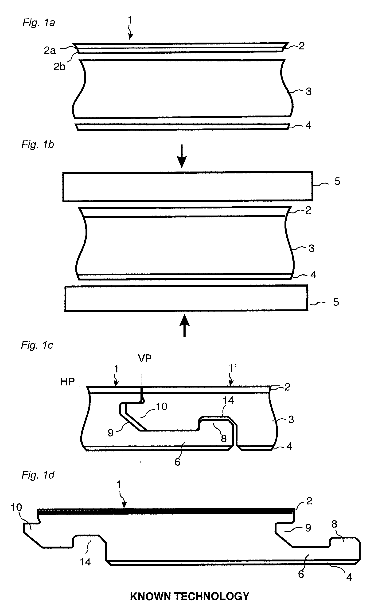
CROSS REFERENCE TO RELATED APPLICATIONS[0001]The present application claims priority to U.S. Provisional Application No. 61 / 667,190 (VA084), filed on Jul. 2, 2012. The entire contents of U.S. Provisional Application No. 61 / 667,190 (VA084) are hereby incorporated herein by reference in their entirety.TECHNICAL FIELD[0002]The disclosure generally relates to the field of forming of panels, e.g. building panels. More particular, the disclosure relates to a method of forming floor panels and floor panels produced by the method.FIELD OF APPLICATION[0003]Embodiments of the present invention are particularly suitable for use in floating floors, which are formed of floorboards which are joined mechanically with a locking system and are made up of one or more upper layers of laminated decorative material, an intermediate core of wood-fibre-based material and a lower balancing layer on the rear side of the core. The following description of known technique, problems of known systems and object...

Claims


Application Information

Patent Timeline
Patent Type & Authority Patents(United States)
IPC IPC(8): E04B2/00E04F15/02E04F15/10E04C2/24
CPCE04C2/246E04F15/02161E04F15/102E04F15/107E04F2201/0161E04F2203/04Y10T428/24777B27F1/04B27F1/00B27F1/02E04F15/02038E04F15/041E04F2201/023E04F2203/08B41J2/03B32B2607/00B32B2471/00B29B13/02B27N3/04B32B3/06B32B21/02
Inventor PERVAN, DARKO
Owner CERALOC INNOVATION AB
Why Eureka
Eureka Blog
Learn More