
Spiking neural network feedback apparatus and methods

a neural network and feedback technology, applied in the field of artificial neural networks, can solve the problems of unstable spiking neural networks that employ positive feedback, invariably unstable, and ‘runaway’ potentiation, so as to reduce increase the effect of connection efficacy, and reduce the probability

Inactive Publication Date: 2015-09-08
BRAIN CORP
View PDF118 Cites 18 Cited by
  • Summary
  • Abstract
  • Description
  • Claims
  • Application Information

AI Technical Summary

Benefits of technology

The invention provides a method for a computerized system to provide a context for a spiking neuron based on an indication of the context and a feed-forward input associated with the neuron. The method also includes reducing the efficacy of a connection when a preceding context input has a negative effect on the neuron and increasing the efficacy of the connection when the preceding context input has a positive effect on the neuron. This allows for context-based spiking and reduces the likelihood of a positive feedback within a loop associated with the neuron. Additionally, the method includes detecting a first context input and decreasing the efficacy of a connection when the first input precedes a response by the neuron. This reduces the likelihood of a subsequent neuronal response based on receipt of a subsequent context input. Overall, the invention provides a more efficient and effective means for processing information in a computerized network.

Problems solved by technology

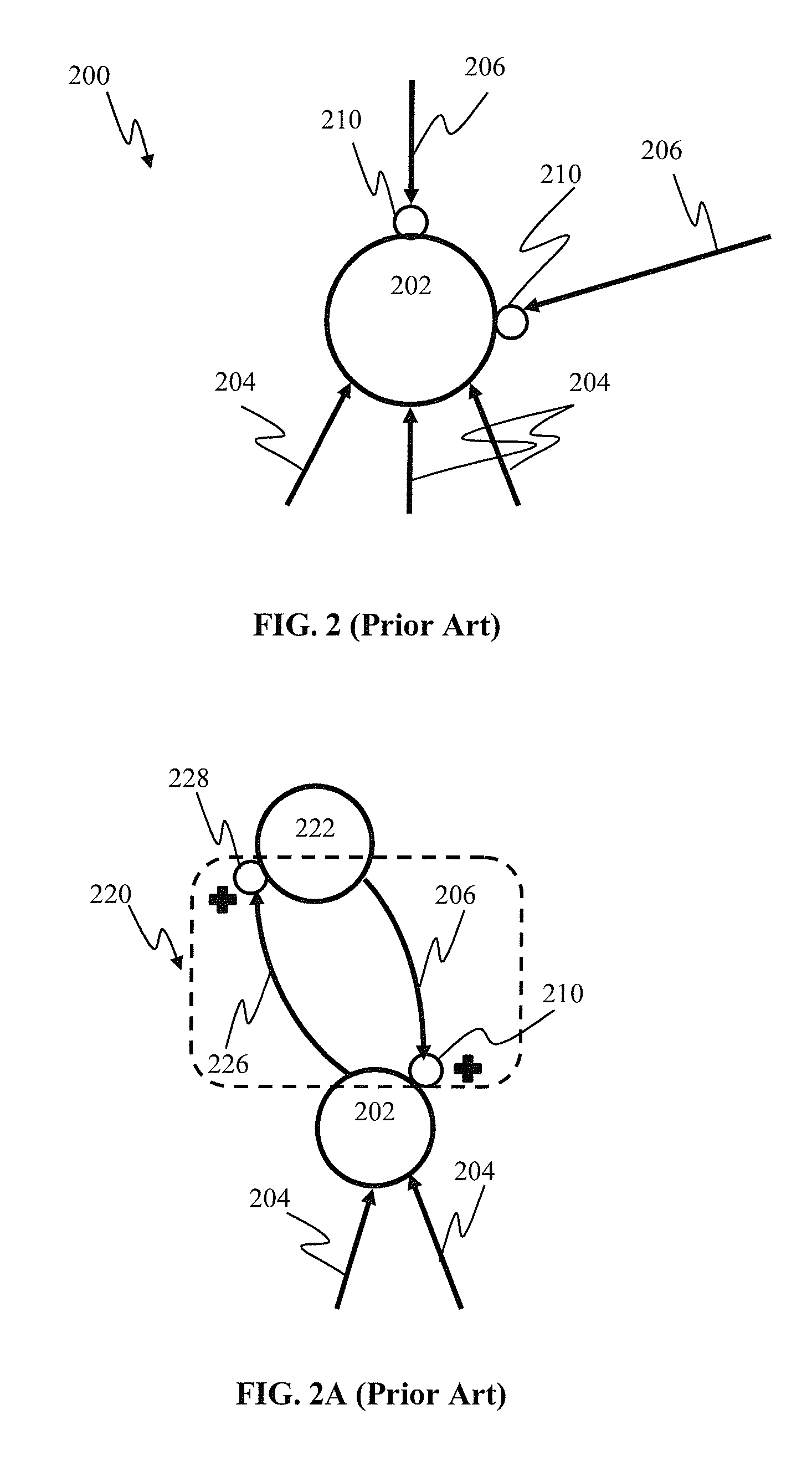
Such positive feedback configurations are invariably unstable, and result in a ‘runaway’ potentiation of synapses (e.g., the 210, 228 in FIG. 2A).
As a result, presently available spiking neural networks that employ positive feedback are often unstable, characterized by uncontrolled spiking, seizures, and / or creation of hallucinatory responses.

Method used


Image

  • Spiking neural network feedback apparatus and methods
  • Spiking neural network feedback apparatus and methods
  • Spiking neural network feedback apparatus and methods

Examples


Embodiment Construction

[0056]Embodiments of the present invention will now be described in detail with reference to the drawings, which are provided as illustrative examples so as to enable those skilled in the art to practice the invention. Notably, the figures and examples below are not meant to limit the scope of the present invention to a single embodiment or implementation, but other embodiments and implementations are possible by way of interchange of or combination with some or all of the described or illustrated elements. Wherever convenient, the same reference numbers will be used throughout the drawings to refer to same or like parts.

[0057]Where certain elements of these embodiments or implementations can be partially or fully implemented using known components, only those portions of such known components that are necessary for an understanding of the present invention will be described, and detailed descriptions of other portions of such known components will be omitted so as not to obscure th...


PUM


Abstract

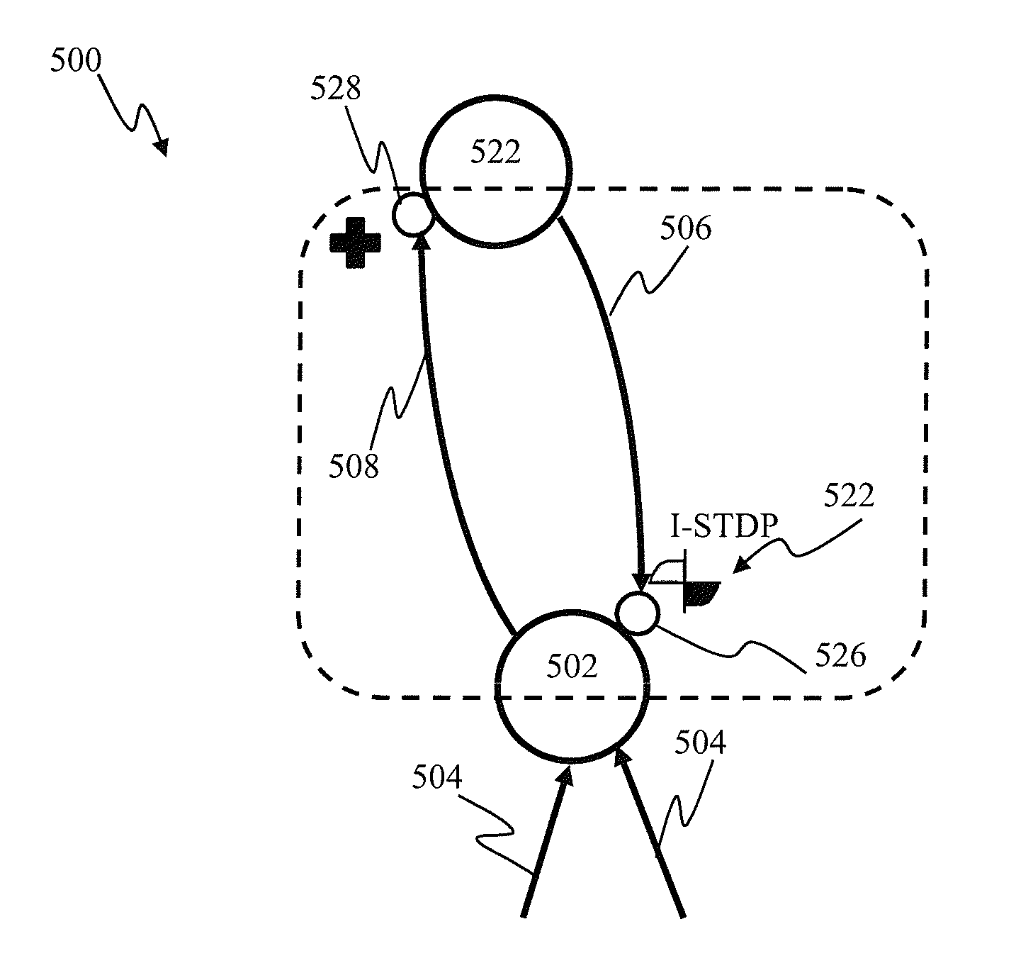
In one approach, spiking neurons receive sensory stimulus and context signal that correspond to the same context. When the stimulus provides sufficient excitation, neurons generate response. Context connections are adjusted according to inverse spike-timing dependent plasticity. When the context signal precedes the post synaptic spike, context synaptic connections are depressed. Conversely, whenever the context signal follows the post synaptic spike, the connections are potentiated. The inverse STDP connection adjustment ensures precise control of feedback-induced firing, eliminates runaway positive feedback loops, and enables self-stabilizing network operation. In another aspect, the connection adjustment methodology facilitates robust context switching when processing visual information. When a context (such an object) becomes intermittently absent, prior context connection potentiation enables firing for a period of time. If the object remains absent, the connection becomes depressed thereby preventing further firing.

Description

CROSS-REFERENCE TO RELATED APPLICATIONS[0001]This application is related to a co-owned U.S. patent application Ser. No. 13 / 465,903 entitled “SENSORY INPUT PROCESSING APPARATUS AND METHODS IN A SPIKING NEURAL NETWORK”, filed contemporaneously herewith on May 7, 2012, and a co-owned U.S. patent application Ser. No. 13 / 465,918 entitled “SPIKING NEURAL NETWORK OBJECT RECOGNITION APPARATUS AND METHODS”, filed contemporaneously herewith on May 7, 2012, each of the foregoing incorporated herein by reference in its entirety. This application is also related to co-owned U.S. patent application Ser. No. 12 / 869,573 entitled “SYSTEMS AND METHODS FOR INVARIANT PULSE LATENCY CODING” filed Aug. 26, 2010, Ser. No. 12 / 869,583 entitled “INVARIANT PULSE LATENCY CODING SYSTEMS AND METHODS SYSTEMS AND METHODS” filed Aug. 26, 2010, Ser. No. 13 / 152,084 entitled “APPARATUS AND METHODS FOR PULSE-CODE INVARIANT OBJECT RECOGNITION” filed Jun. 2, 2011, Ser. No. 13 / 152,105 entitled “APPARATUS AND METHODS FOR TE...

Claims


Application Information

Patent Timeline
Patent Type & Authority Patents(United States)
IPC IPC(8): G06F15/18G06N3/04
CPCG06N3/049G06N3/088
Inventor PIEKNIEWSKI, FILIPIZHIKEVICH, EUGENESZATMARY, BOTONDPETRE, CSABA
Owner BRAIN CORP
Learn More