[0005]A problem of note in wireless networks is the interference presented to users in one Cell coverage area by the signals transmitted by an adjacent Cell. This interference is called Inter-Cell Interference, and is especially encountered by users who are near the boundary between two adjacent Cells. The RF signal from each Cell necessarily overlaps the coverage area of the adjacent Cell, because otherwise, RF coverage holes result. The areas where the RF signals overlap are the areas in which Inter-Cell Interference occurs. Because of the interference, the data rates offered to users located in the Cell boundary areas may be reduced, and hence the Cell capacity and throughput, as well as the user experience, may be impacted in a negative way. In an LTE Wireless Network, users are assigned sub-carriers on which to transmit or receive their data. The sub-carrier sets are designed in the standards to be orthogonal to each other, so that users assigned to one set of sub-carriers observe no interference from the transmissions for other users who are assigned a different set of sub-carriers. However, near the Cell boundary, each of two adjacent Cells may assign the same set of sub-carriers to users in its respective Cell boundary area, which is part of its Cell coverage area. In this case, each of these users may be interfered with by the transmissions in the adjacent Cell that use the same sub-carriers as are assigned to the given user.
[0006]One current technique for reducing inter-Cell interference includes dividing the LTE band of sub-carriers into subsets, such that one subset of sub-carriers is assigned only to users near a boundary of the serving Cell, while the second subset is assigned to users located in the interior of the serving Cell. The subsets may be arranged in each of a set of adjacent Cells such that different subsets of sub-carriers are used at the boundary of these Cells. This approach results in lower Cell throughput and possibly lower maximum data rates, because not all of the LTE sub-carriers are available for assignment to any user. Another current technique uses inter-Cell communications to inform an adjacent Cell of the sub-carriers that are being assigned, so they may not be assigned by the adjacent Cell. This technique suffers from the added inter-Cell communications, a less than optimal Cell throughput, and possibly from lower maximum data rates that may be assigned to users.
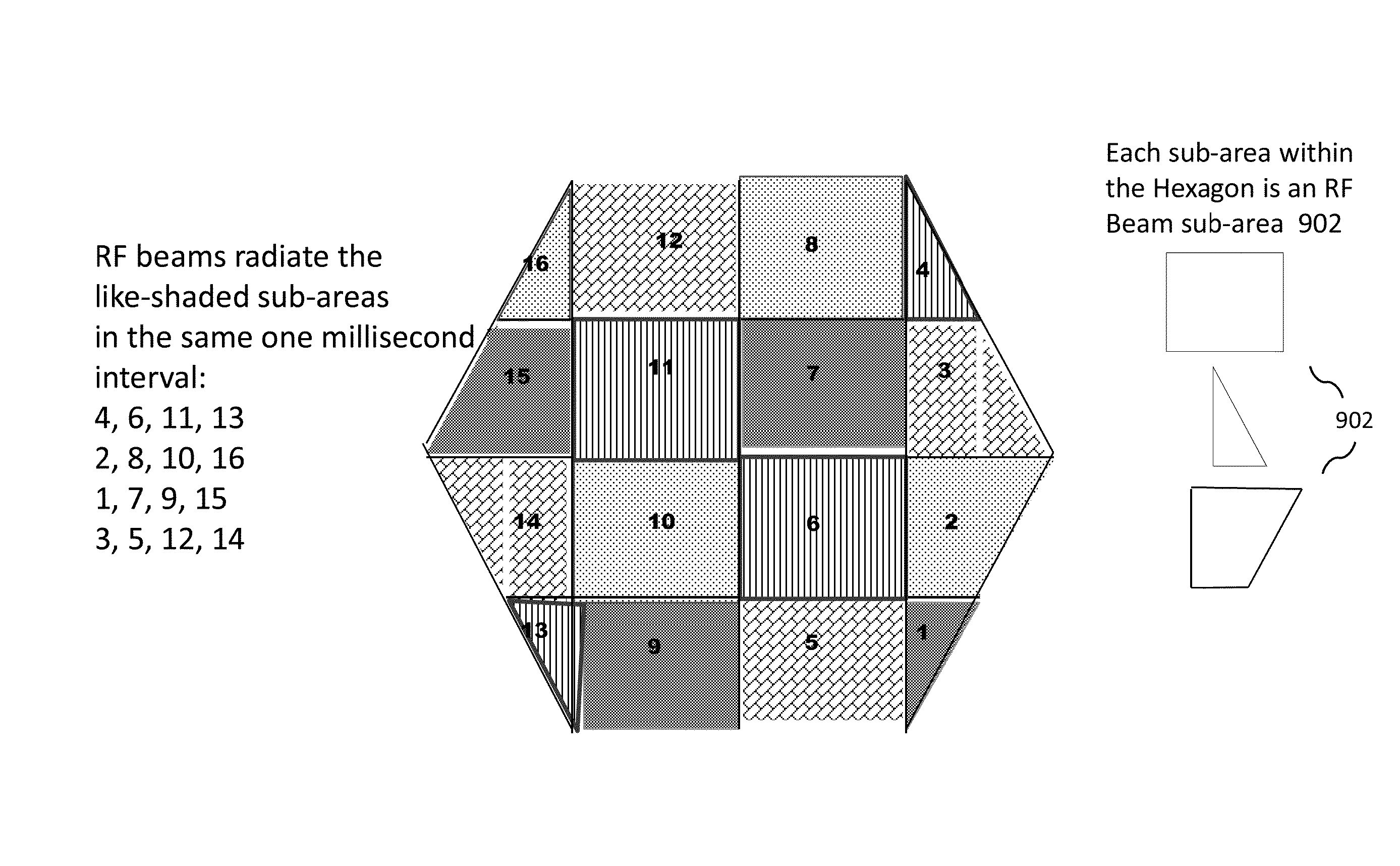
[0007]The present disclosure describes a method of assigning beam rotation patterns in adjacent Cells for minimizing Inter-Cell Interference while allowing the complete set of LTE sub-carriers to be assigned to any user at any time, and without requiring additional Cell-to-Cell communications. This part of the disclosure pertains to a collection of Cells in an LTE wireless network that employs an Agile Beam Forming technique to transmit and receive RF signals. In an LTE FDD system, a set of sixteen RF beam sub-areas may be selected to cover the area normally covered by the Cell transmissions / receptions in an LTE FDD system that does not use Agile Beam Forming. Each sub-area is covered by the transmission (or reception) of a particular RF beam that is generated by the antenna system. In this instance, the set of sixteen RF beam sub-areas may be grouped into four subsets of four RF beam sub-areas each, where the geographical separation between sub-areas in the same subset is selected to be as large as possible. Within a given Cell using Agile Beam Forming techniques, it is then possible to assign the same set of sub-carriers to four different users who are located in different RF beam sub-areas, thus increasing the effective system bandwidth by a factor of up to four, and likewise, increasing the effective system throughput by a factor of up to four. Although an example using sixteen RF beam sub-areas broken into to four subsets is described, one skilled in the art will appreciate that other configurations may be used in implementation of the system, and as applied to the disclosed technique for reducing inter-Cell interference.
[0021]In embodiments, in each TTI in an FDD system, or in each D sub-frame in a TDD system, the MAC layer software and the PHY layer software may generate (N+1) digital data streams, where one corresponds to the transmit RF signal to be generated in the current TTI, and which covers the entire Cell (e.g., Cell-Wide transmit RF signal), and where each of the remaining N digital data steams corresponds to an RF transmit beam to be generated in the TTI. The MAC layer software may provide the PHY layer software with information regarding which transmit data stream to use to transmit a specific set of transport blocks using a specific set of PRBs, be they for common channels, or for user data. The PHY layer software may process the transport blocks received from the MAC layer software, placing the results in a transmit beam data stream, or in the Cell-Wide transmit data stream, in the interface to the RF and antenna system, per the instructions received from the MAC layer software.
[0027]In embodiments, in each TTI in an FDD system, or in each U sub-frame in a TDD system, the RF and antenna system may generate (N+1) digital data streams, where one corresponds to the received RF signal that covers the entire Cell (e.g., the Cell-Wide receive data stream), and where each of the remaining N digital data steams corresponds to an RF receive beam generated in the TTI. The MAC layer software may provide the PHY layer software with information regarding which receive data stream to process to receive a specific set of PRBs, be they for common channels, or for user data. The PHY layer software may present to the MAC layer software the results of its processing for each of the (N+1) receive signals, and for each result, may provide an indication of the receive beam data stream from which the result is obtained. By providing an indication of the receive beam data stream from which each result is obtained, the system allows the same PRB to be detected in multiple receive data streams.