Octane separation system and operating method

a separation system and octane technology, applied in the direction of machines/engines, electrical control, exhaust treatment electric control, etc., can solve the problems of high pressure and temperature in the combustion chamber during high torque operation, inability to adjust the octane separation threshold, and inability to reduce so as to reduce or eliminate the staleness of fuel, increase secondary combustion efficiency, and be readily combustible

Inactive Publication Date: 2015-09-01
FORD GLOBAL TECH LLC
View PDF46 Cites 6 Cited by
  • Summary
  • Abstract
  • Description
  • Claims
  • Application Information

AI Technical Summary

Benefits of technology

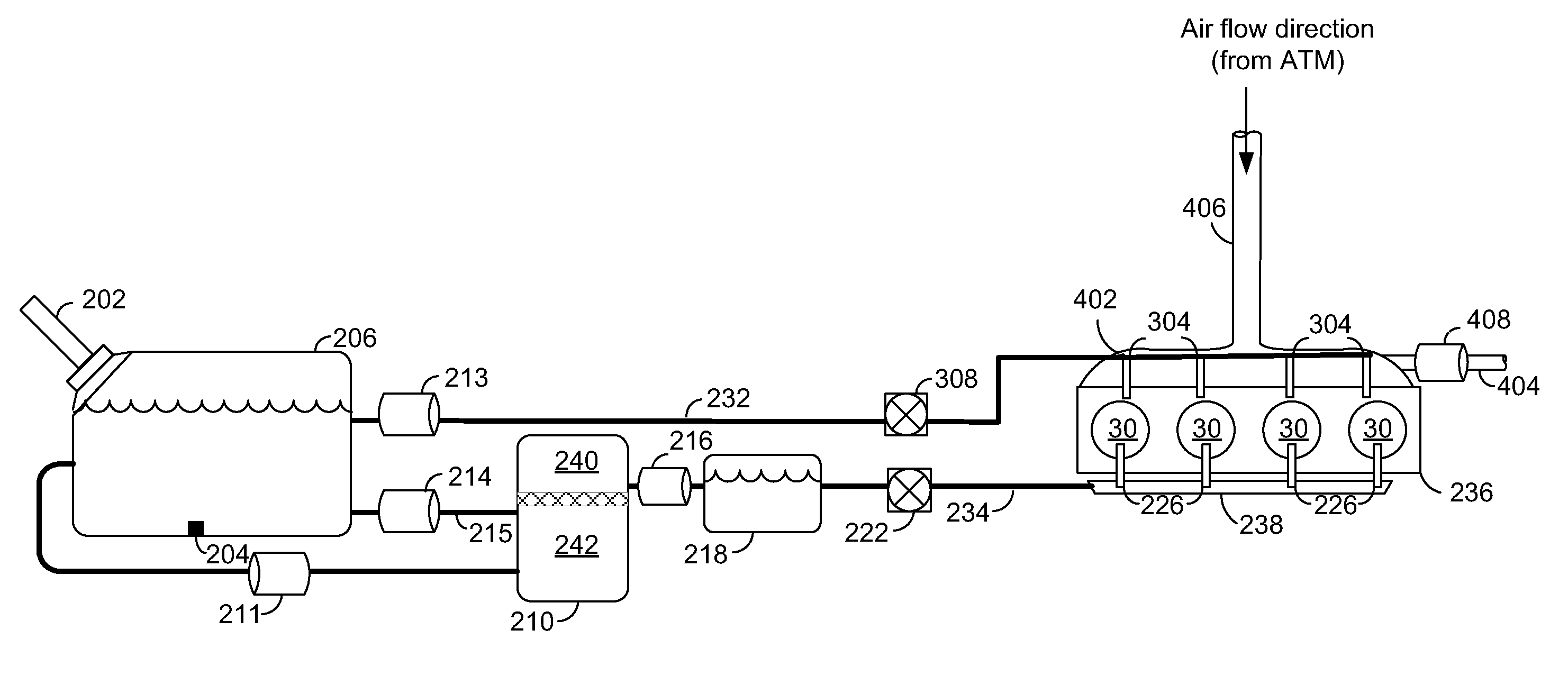
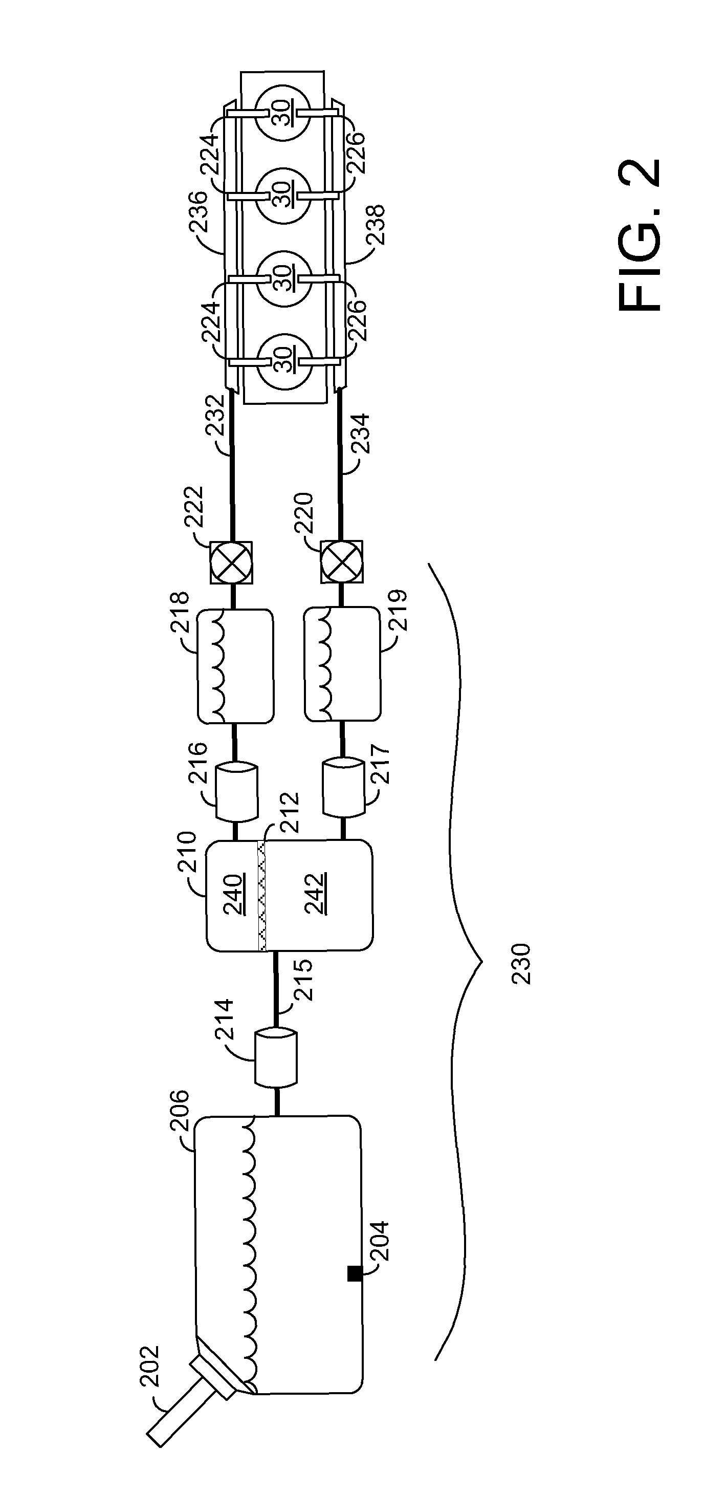
[0006]The inventors herein found that by separating fuel by octane level, the desired octane separation threshold may be set at a number of values to achieve precise combustion control. Further, by separating fuel into a high octane portion and a low octane portion and returning the low octane portion to the externally filled fuel tank (or vice versa) fuel separation advantages may be achieved without adding a third fuel pump and tank, lessening both the weight and space occupied by the separation system, and decreasing the system cost. A fuel separator may have a higher low octane output or a higher high octane output. Thus the separation tank may be smaller than the externally filled fuel tank and may store the fuel with an octane rate corresponding to lower separator output to further minimize the volume occupied by the separation system and the system weight and to effectively transform the externally filled fuel tank into a high octane fuel tank or a low octane fuel tank.

Problems solved by technology

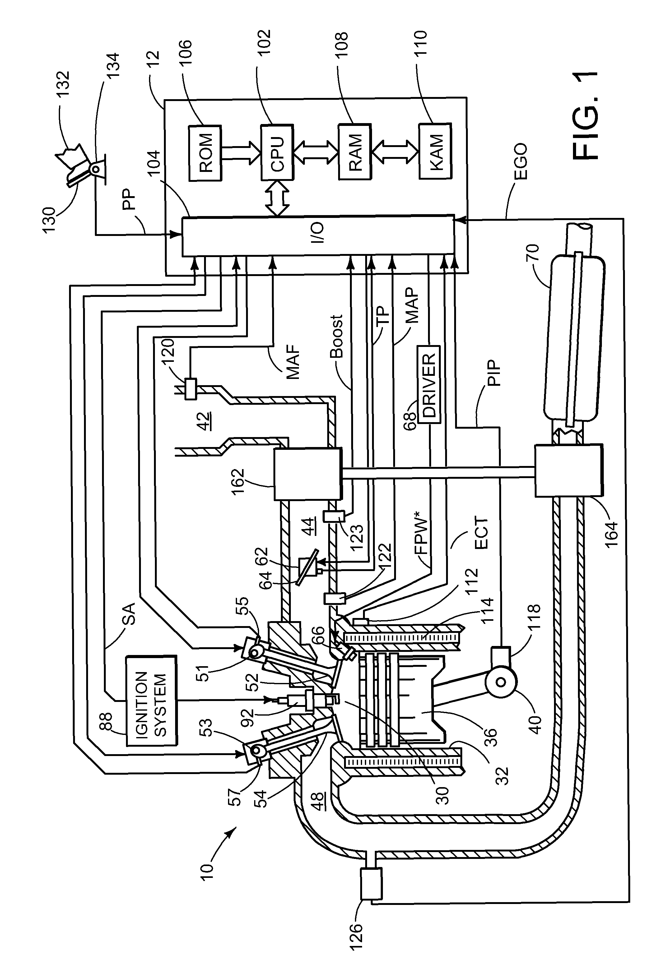
High torque demands may be met by increased airflow into a combustion chamber, thus a combustion chamber may have high pressure and temperature during high torque operation.
If chamber conditions reach the auto-ignition conditions of the air-fuel mixture located therein, pre-ignition or engine knock may occur.
Further, this method does not allow for a variable octane separation threshold.
Many vehicles however have limited available space and therefore cannot accommodate a three fuel tank and three fuel pump configuration.
Further, this method adds additional weight to the vehicle contributing to fuel efficiency losses, and the method is also high cost.
Prior fuel separation approaches experience fuel staleness after extended operation at a limited range of speed-loads.
Alternatively, a vehicle may be operated almost exclusively at idle and light loads, thus high octane fuel may almost never be used.
Therefore fuel in the underused tank may become stale after a period of time.

Method used


Image

  • Octane separation system and operating method
  • Octane separation system and operating method
  • Octane separation system and operating method

Examples


Embodiment Construction

[0018]Gasoline contains a large number of hydrocarbon compounds used for combustion. Compounds such as isooctane (C8H18), butane (C4H10), 3-ethyitoluene (C9H12), and octane enhancer methyl tert-butyl ether (C5H12O) are commonly found in gasoline, each having a respective octane rating and energy density. Ethanol (C2H6O) is also commonly found in blended gasoline and has a higher octane rating and lower energy density than unblended gasoline.

[0019]Octane rating and, synonymously, octane level refer to conditions that a fuel-air mixture can withstand without igniting. Higher octane fuels may withstand higher pressure and temperature within a combustion chamber without auto-igniting than lower octane fuels.

[0020]Under normal applied ignition conditions, combustion is initiated in a combustion chamber via a spark containing an air fuel mixture between 10 and 40 crankshaft degrees prior to top dead center. This allows for the combustion process to develop peak pressure at a time allowing...


PUM


Abstract

An engine method, comprising delivering high octane fuel to a high octane fuel tank and delivering low octane fuel to a low octane fuel tank and injecting atmospheric air into an exhaust system for secondary air injection in response to delivering low octane fuel to an engine.

Description

BACKGROUND AND SUMMARY[0001]Gasoline used in engine combustion contains a large number of compounds, typically including dozens or hundreds of hydrocarbons plus alcohol. Each of these compounds may have different energy densities and knock properties or “octane” inherent to their chemical composition and structure.[0002]The octane of a fuel is the ease at which the fuel auto-ignites. A fuel's octane may be classified by its tendency to ignite under variable pressure or temperature conditions. An octane rating is a standard procedure for quantifying the conditions at which a fuel auto-ignites without external ignition. Compounds with higher octane ratings may withstand greater temperature within a combustion chamber without auto-igniting. High torque demands may be met by increased airflow into a combustion chamber, thus a combustion chamber may have high pressure and temperature during high torque operation. If chamber conditions reach the auto-ignition conditions of the air-fuel mi...

Claims


Application Information

Patent Timeline
Patent Type & Authority Patents(United States)
IPC IPC(8): F01N3/00F02D19/06F01N3/22F02D41/06F02D41/00F02P5/152
CPCF02D19/0649F01N3/22F02D19/0665F02D19/0671F02D41/0025F02D41/064F02P5/1527Y02T10/30F01N3/05F01N9/00F02M37/0088F01N2900/08
Inventor LEONE, THOMAS G.
Owner FORD GLOBAL TECH LLC
Why Eureka
Try Eureka