
Power transmission apparatus

a technology of transmission apparatus and power supply, which is applied in the direction of automatic control system, hybrid vehicles, instruments, etc., can solve the problems of reducing the operation feeling of the actuator used by the operator and reducing the operating speed of the actuator, so as to prevent the flow rate of hydraulic oil discharged by the hydraulic pump, suppress the number of revolutions of the hydraulic pump, and reduce the effect of wasteful fuel consumption

Inactive Publication Date: 2015-08-25
YANMAR POWER TECHNOLOGY CO LTD
View PDF6 Cites 2 Cited by
  • Summary
  • Abstract
  • Description
  • Claims
  • Application Information

AI Technical Summary

Benefits of technology

[0014]The embodiments of the present invention provide the following advantageous effects.
[0015]According to one aspect of the present invention, when the working hydraulic actuator is operated, the engine is stopped, whereby the wasteful fuel consumption can be suppressed. When the engine is restarted, the hydraulic pump is driven by the electric motor until the number of revolutions of the engine reaches a predetermined value or more. After the number of revolutions of the engine reaches the predetermined value or more, the hydraulic pump is driven by the engine. Accordingly, even when the number of revolutions of the engine is low immediately after the restart of the engine, the reduction of the number of revolutions of the hydraulic pump can be prevented and the reduction of the flow rate of the hydraulic oil discharged by the hydraulic pump can be prevented. Therefore, the deterioration of the operation feeling of the working hydraulic actuator at the time of restarting the engine can be prevented.
[0016]Further, the clutch is disconnected at the time of restarting the engine, so that the addition of the starting torque of the hydraulic pump to the engine can be prevented. Consequently, even when the viscosity of the hydraulic oil is high, in particular, in the low temperature environment, and the starting torque of the hydraulic pump becomes higher than the starting torque in an ordinary temperature, the deterioration of the startability of the engine can be prevented.
[0017]According to another aspect of the present invention, when the absorbing horsepower of the hydraulic pump is low (in light load works), the hydraulic pump can be driven only by the electric motor without starting the engine. Accordingly, the fuel consumption can be suppressed, and the hydraulic pump can be driven by the electric motor that has large low-speed torque and enables smooth rotation, and the workability can be improved.
[0018]According to another aspect of the present invention, the operator can arbitrarily select whether to carry out the idling stop control.

Problems solved by technology

Accordingly, there is a disadvantage in that the operating speed of the actuator is reduced, and the operation feeling of the actuator used by the operator deteriorates.

Method used


Image

  • Power transmission apparatus
  • Power transmission apparatus
  • Power transmission apparatus

Examples


Embodiment Construction

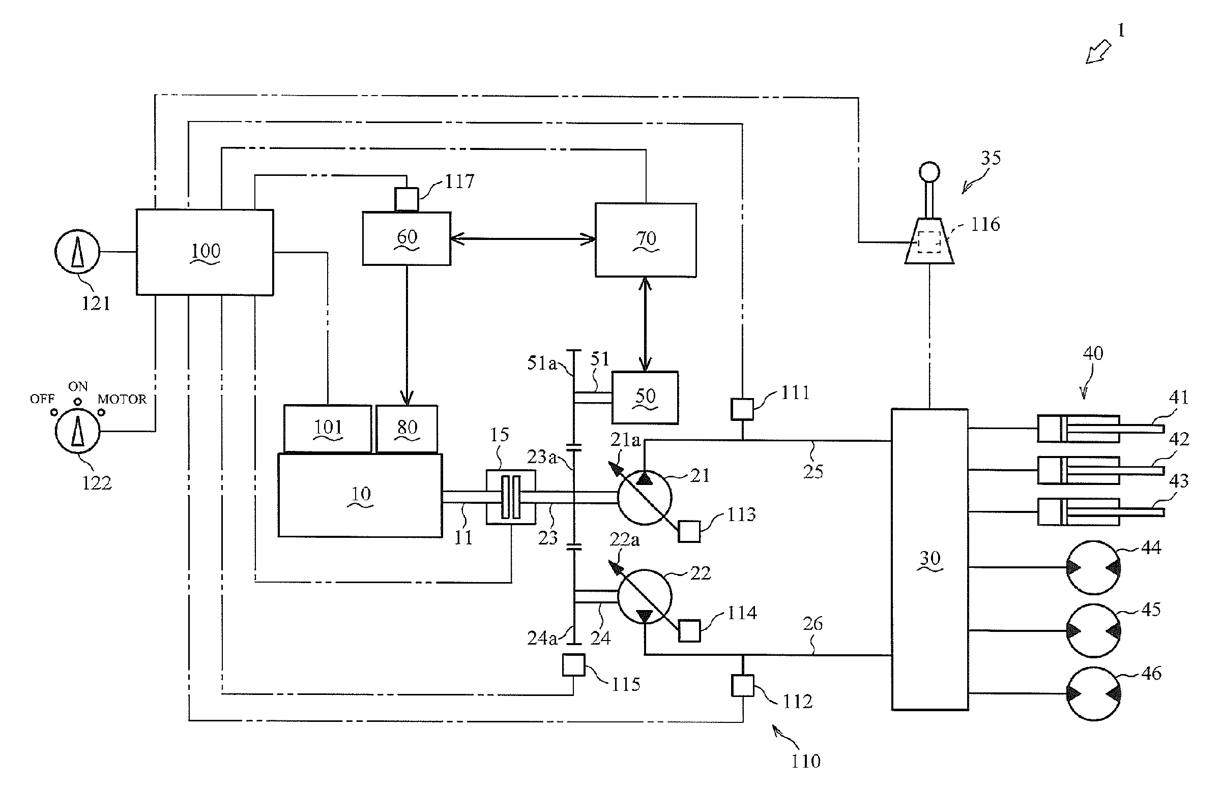
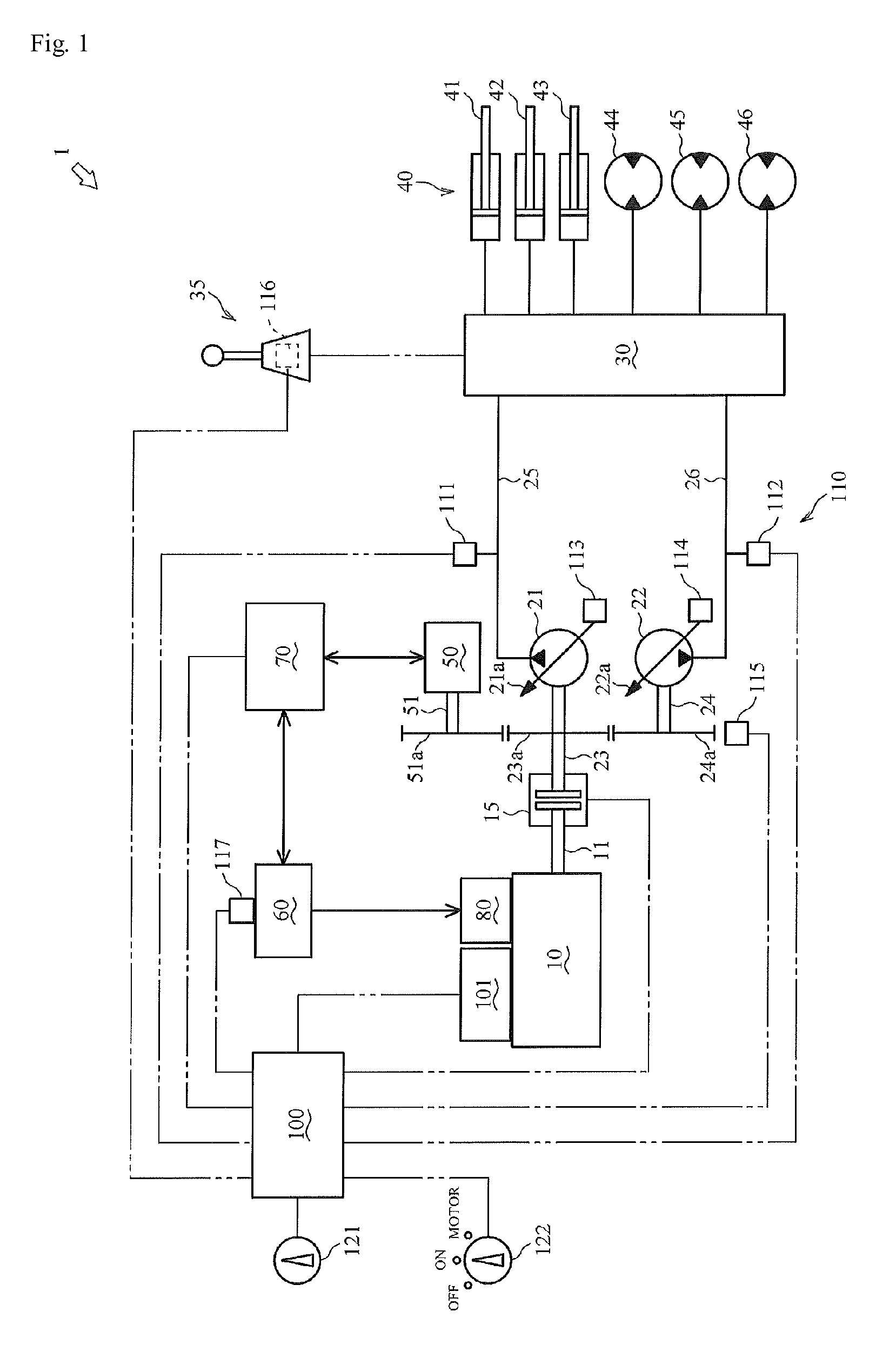
[0046]Hereinafter, a power transmission apparatus 1 according to a first embodiment of the present invention will be described referring to FIG. 1.

[0047]The power transmission apparatus 1 transmits motive power from a driving source and drives various actuators.

[0048]The power transmission apparatus 1 includes an engine 10, a first hydraulic pump 21, a second hydraulic pump 22, a clutch 15, a control valve 30, a working hydraulic actuator 40, an operating means 35, a motor generator 50, a battery 60, an inverter 70, a cell motor 80, an absorbing horsepower detecting means 110, an operating state detecting means 116, a charging state detecting means 117, an engine revolution setting means 121, an idling stop selecting means 122, an engine controller unit 101, and a main controller 100.

[0049]The power transmission apparatus 1 according to the embodiment of the present invention is included in a hydraulic excavator, but is not limited to this. That is, the power transmission apparatus ...


PUM


Abstract

The power transmission apparatus may include a control device to carry out idling stop control in such a manner that, when it is detected that an operating means is not operated for a predetermined time or more, an engine is stopped, and a clutch is disconnected, and the supply of the electric power from a battery to a motor generator is interrupted, and when it is detected that the operating means is operated afterwards, the engine is started by a cell motor, and the supply of the electric power from the battery to the motor generator is permitted, and the clutch is connected after the number of revolutions Ne of the engine reaches a predetermined value or more, and the supply of the electric power from the battery to the motor generator is interrupted.

Description

[0001]This is the U.S. National Stage of Application No. PCT / JP2011 / 074295, filed on 21 Oct. 2011. Priority under 35 U.S.C. §119(a) and 35 U.S.C. §365(b) is claimed from Japanese Application No. 2010-241105, filed 27 Oct. 2010, the disclosure of which is also incorporated herein by reference.TECHNICAL FIELD[0002]The present invention relates to a technology of a power transmission apparatus in which an engine and an electric motor are used.BACKGROUND ART[0003]Conventionally, there has been known a technology regarding a power transmission apparatus in which an engine is automatically stopped or started in predetermined cases. For example, see the description disclosed by patent document 1.[0004]The power transmission apparatus disclosed by patent document 1 includes an engine which serves as a power source, a hydraulic pump to discharge hydraulic oil, a clutch interposed between an output shaft of the engine and an input shaft of the hydraulic pump, an electric motor (electric motor...

Claims


Application Information

Patent Timeline
Patent Type & Authority Patents(United States)
IPC IPC(8): B60W20/00F02D29/04F02D29/02E02F9/20B60W10/02E02F9/22B60W10/06B60W10/26
CPCB60W20/40B60W10/02B60W10/06B60W10/26E02F9/2075E02F9/2079E02F9/2246E02F9/2292E02F9/2296F02D29/02F02D29/04B60W2600/00Y10S903/93B60W20/20B60W20/11B60W10/08B60W2300/17Y02T10/62B60W2556/00
Inventor OGATA, NAGAHIROMIYAKAWA, KENJI
Owner YANMAR POWER TECHNOLOGY CO LTD
Learn More