
Stabilisation method and computer system

a computer system and stabilisation method technology, applied in the field of stabilisation methods and computer systems, can solve the problems of introducing perceptible latency/delay or mask slow, generating noise or moderating the accuracy of the digital expression of the continuous physical variable, and only able to output discrete readings of the variable, so as to prevent the introduction of noticeable delay and reliably filter noise

Active Publication Date: 2015-07-28
SOFTKINETIC SOFTWARE
View PDF15 Cites 0 Cited by
  • Summary
  • Abstract
  • Description
  • Claims
  • Application Information

AI Technical Summary

Benefits of technology

Effectively suppresses noise in digital sensor measurements while preserving slow, steady variations, ensuring accurate representation of physical variables without noticeable delay, suitable for various digital sensors including 3D imaging systems.

Problems solved by technology

While physical variables are usually continuous signals, digital sensors can only output discrete readings of those variables.
The discrete readings of such a continuous physical variable by a digital sensor may generate some noise or modify the accuracy of the digital expression of the said continuous physical variable.
While filters may be applied to reduce or suppress such noise, they may then also introduce perceptible latency / delay or mask slow, but definite, variations along the series of measures of said physical variable.
In particular when the capture of such a spatial position measurement also involves an object recognition step, the object recognition algorithm may induce significant noise in successive measurements of the spatial position of the object, noise which may be aggravated by the limited definition of the spatial positioning raster.
However, such a stabilisation technique could lead to a slow, but real continuous motion being unnoticed or reflected as a jerking variation in the position measurements.

Method used


Image

  • Stabilisation method and computer system
  • Stabilisation method and computer system
  • Stabilisation method and computer system

Examples


Embodiment Construction

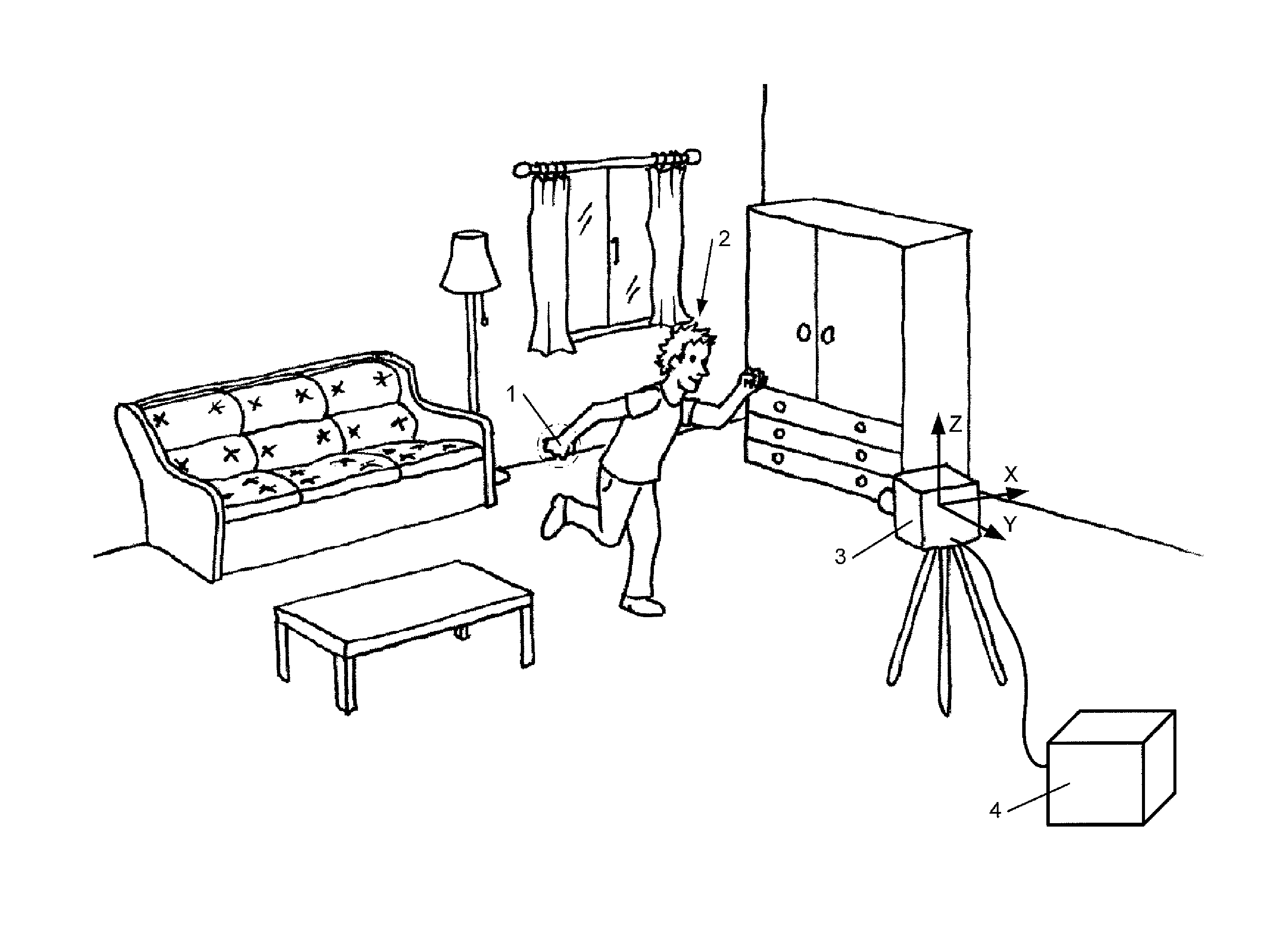
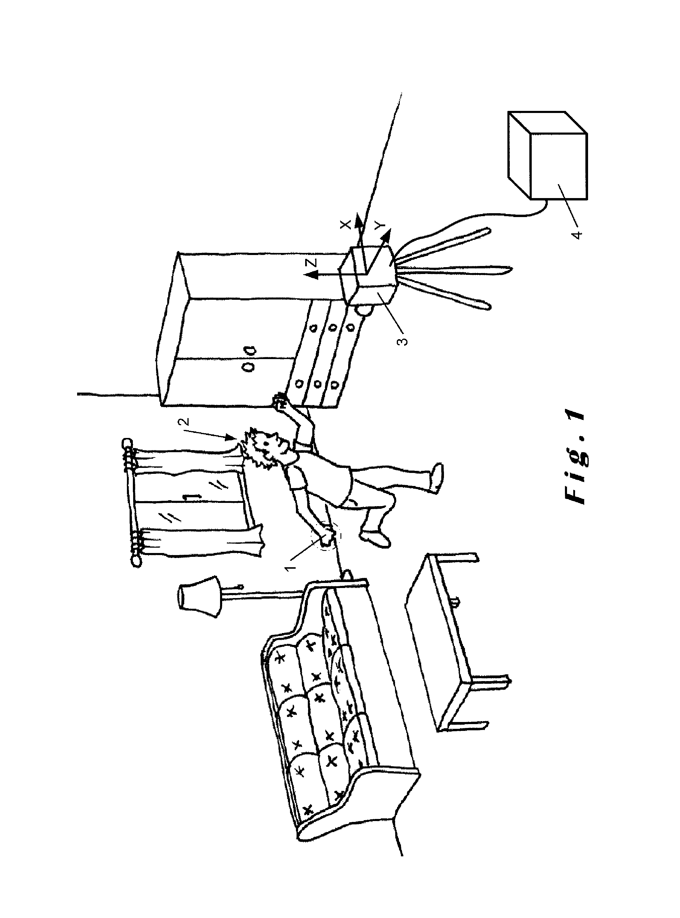
[0038]A specific embodiment of the invention is illustrated in FIG. 1. In this particular embodiment, the method of the invention is used to stabilise the motion of the right hand 1 of a human user 2 as perceived through a 3D imaging sensor 3 connected to a computer system 4. In a particularly advantageous embodiment, the 3D imaging sensor 3 is a TOF camera. However, other types of digital imaging systems, such as 2D cameras, stereo cameras, LIDAR, radar, sonar, etc. may alternatively be used.

[0039]The 3D imaging sensor 3 captures 3D image data of the room in which the human user 2 stands, comprising a 2D image of the room with a plurality of pixels and a depth value for each pixel corresponding the distance to the 3D imaging sensor 3 of the point imaged by that pixel. Since the X and Y positions of the pixels in the 2D image themselves correspond to zenith and azimuth angles of the points they represent with respect to the 3D imaging sensor 3, these 3D image data can be illustrated...


PUM


Abstract

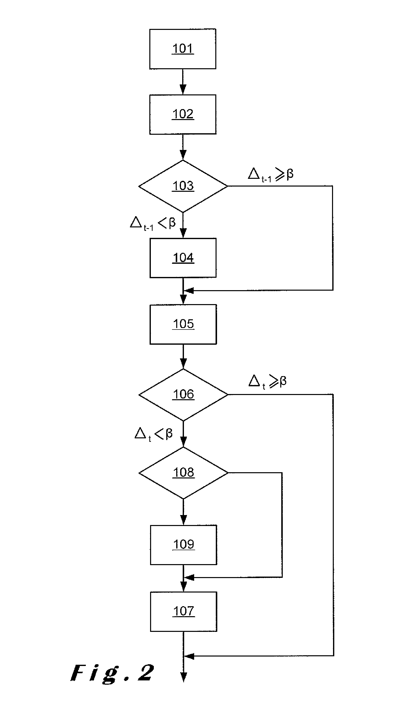
The present invention relates to a method for stabilizing a series of measurements of a physical variable captured by a digital sensor. This method comprises the steps of: capturing at least a first measurement, a second measurement, and a third measurement of said physical variable and storing each measurement in a digital memory. The first and second measurements are compared and, if a difference between the first measurement and the second measurement is below a predetermined threshold, the second measurement is replaced in the memory by a corrected second measurement where the difference with respect to said first measurement has been reduced using a first filtering strength. The corrected second measurement and the third measurement are compared and, if a difference between the filtered value of the corrected second measurement and said third measurement is also below the threshold, said the third measurement is replaced by a corrected third measurement where a difference with respect to said corrected second measurement has been reduced using a second filtering strength that is lower than the first filtering strength. This method has the advantage of filtering noise while still allowing slow but relevant variations in the series of measurements.

Description

CROSS REFERENCE TO RELATED APPLICATION[0001]This application is a National Stage of International Application No. PCT / EP2010 / 070819 filed Dec. 28, 2010, claiming priority based on European Patent Application No. 09180784.2 filed Dec. 28, 2009, the contents of all of which are incorporated herein by reference in their entirety.TECHNICAL FIELD[0002]The present invention relates to methods and devices for stabilising a series of measurements of a physical variable captured by a digital sensor.BACKGROUND OF THE INVENTION[0003]While physical variables are usually continuous signals, digital sensors can only output discrete readings of those variables. The discrete readings of such a continuous physical variable by a digital sensor may generate some noise or modify the accuracy of the digital expression of the said continuous physical variable. While filters may be applied to reduce or suppress such noise, they may then also introduce perceptible latency / delay or mask slow, but definite, ...

Claims


Application Information

Patent Timeline
Patent Type & Authority Patents(United States)
IPC IPC(8): G09G5/00G06T5/00G06T5/50G06F17/18G06T7/00G06F3/01G06K9/40G06V10/30
CPCG06T7/004G06F3/011G06F17/18G06T5/002G06T5/50G06K9/40G06T2200/24G06T2207/10016G06T2207/30196A63F2300/1093A63F2300/6045G06T7/70G06V10/30G06T5/70G06T7/00G06T5/00
Inventor BAELE, XAVIERTHOLLOT, JULIEN
Owner SOFTKINETIC SOFTWARE
Learn More