Fixing device and image forming apparatus including same
a technology of fixing device and image forming apparatus, which is applied in the direction of electrographic process apparatus, instruments, optics, etc., can solve the problems of uneven temperature of fixing roller, large amount of process energy, and image quality, and achieve the effect of suppressing excess power supply, reducing uneven temperature, and improving formed image quality
- Summary
- Abstract
- Description
- Claims
- Application Information
AI Technical Summary
Benefits of technology
Problems solved by technology
Method used
Image
Examples
first embodiment
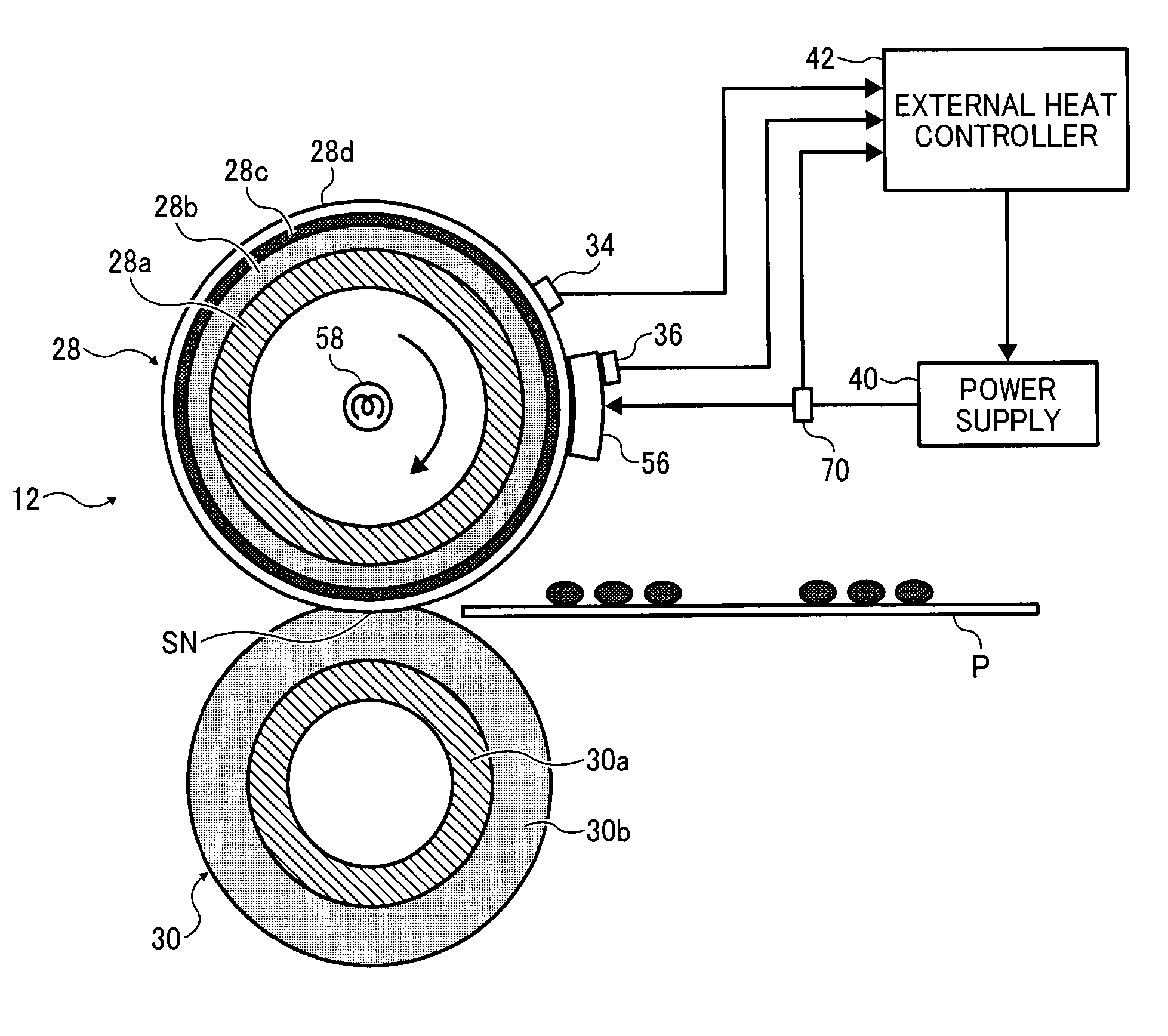
[0036]As illustrated in FIGS. 2 and 3, the fixing device 12 employs an external heating method. That is, the fixing device 12 is constructed of a fixing roller 28, a pressure roller 30, a thermal heater 56, a heat sensor 70, and the like. The fixing roller 28 rotatably contacts an unfixed-image to serve as a fixing member. The pressure roller 30 presses against the fixing roller 28 and forms a fixing nip portion SN along with the fixing roller 28. The thermal heater 56, located outside the fixing roller 28 and supplied with power from a commercial power supply 40, heats the fixing roller. The heat sensor 70 detects heating of each heating element of the thermal heater 56. The thermal heater 56 and the power supply 40 construct an external heater means.
[0037]The thermal heater 56 is constructed of multiple heating elements 56a, 56b, 56c, 56d, 56e, 56f, and 56g, which are disposed at equal intervals in the width direction of the sheet P. Each heating element 56a, 56b, 56c, 56d, 56e, ...
second embodiment
[0065]Next, as described referring to FIGS. 6 and 7, the fixing device 12 according to the present invention will be described.
[0066]FIG. 6 is a schematic cross-sectional view of the fixing device 12 according to the second embodiment of the present invention. The fixing device 12 according to the second embodiment includes a thermal or ceramic heater 56. The heater 56 is constructed of a planar base and heating elements formed on the planar base. The thermal heater 56 is disposed inside a belt or film and provides heat to the belt or film to increase temperature, so that the unfixed image conveyed to the fixing nip portion SN is heated and fixed.
[0067]The thermal heater 56 is disposed upstream of the fixing nip portion SN because a certain length of time is required for the heat from the thermal heater 56 disposed inside the belt or film to reach a surface of the fixing roller 28. Alternatively, the thermal heater 56 may be disposed in the vicinity of the fixing nip portion SN. Thi...
fourth embodiment
[0074]FIG. 9 illustrates a fixing device 12 according to the present invention.
[0075]As illustrated in FIG. 9, the fixing device 12 includes a fixing belt 38 as a fixing rotary member, a pressure roller 30 as an opposite member configured to contact the fixing belt 38 and form a nip portion SN, and a heater 56 configured to heat the fixing belt 38. A contact surface between the heater 56 and the fixing belt 38 is a substantially flat plane.
[0076]The fixing belt 38 is formed of a thin, flexible endless belt. Specifically, the fixing belt 38 is constructed of a base member 38a formed of a stainless steel (SUS) having an external diameter of 40 mm and a thickness of 40 μm, an elastic layer 38b coated to have a thickness of 100 μm on a circumferential surface of the base member 38a, and a release layer 38c formed of fluorine resins such as tetrafluoroethylene-perfluoroalkyl vinylether copolymer (PFA) or polytetrafluoroethylene (PTFE) coated to have a thickness of from 5 μm to 50 μm on a...
PUM
 Abstract
Description
Claims
Application Information
 - R&D
- Intellectual Property
- Life Sciences
- Materials
- Tech Scout
- Unparalleled Data Quality
- Higher Quality Content
- 60% Fewer Hallucinations
Browse by: Latest US Patents, China's latest patents, Technical Efficacy Thesaurus, Application Domain, Technology Topic, Popular Technical Reports.
© 2025 PatSnap. All rights reserved.Legal|Privacy policy|Modern Slavery Act Transparency Statement|Sitemap|About US| Contact US: help@patsnap.com


