
Biological fluid sampling and storage apparatus for remote use

a biological fluid and remote use technology, applied in the field of biological fluid collection and storage, can solve the problems of time-consuming manual hole punching for sample removal and potential distortion, and achieve the effect of increasing drying speed and being easy to separa

Active Publication Date: 2015-05-26
SPOT BIOSCI LLC
View PDF8 Cites 22 Cited by
  • Summary
  • Abstract
  • Description
  • Claims
  • Application Information

AI Technical Summary

Benefits of technology

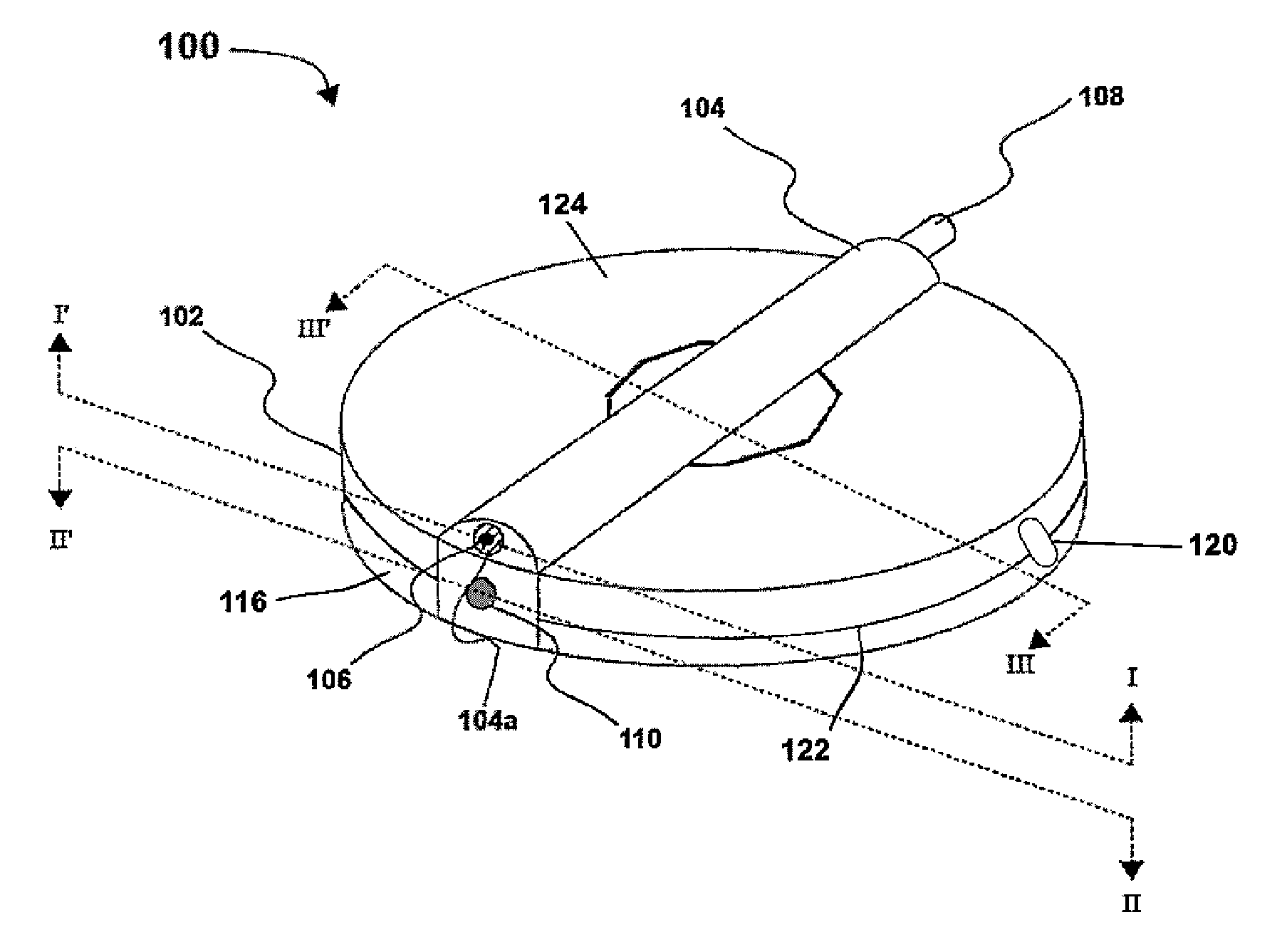
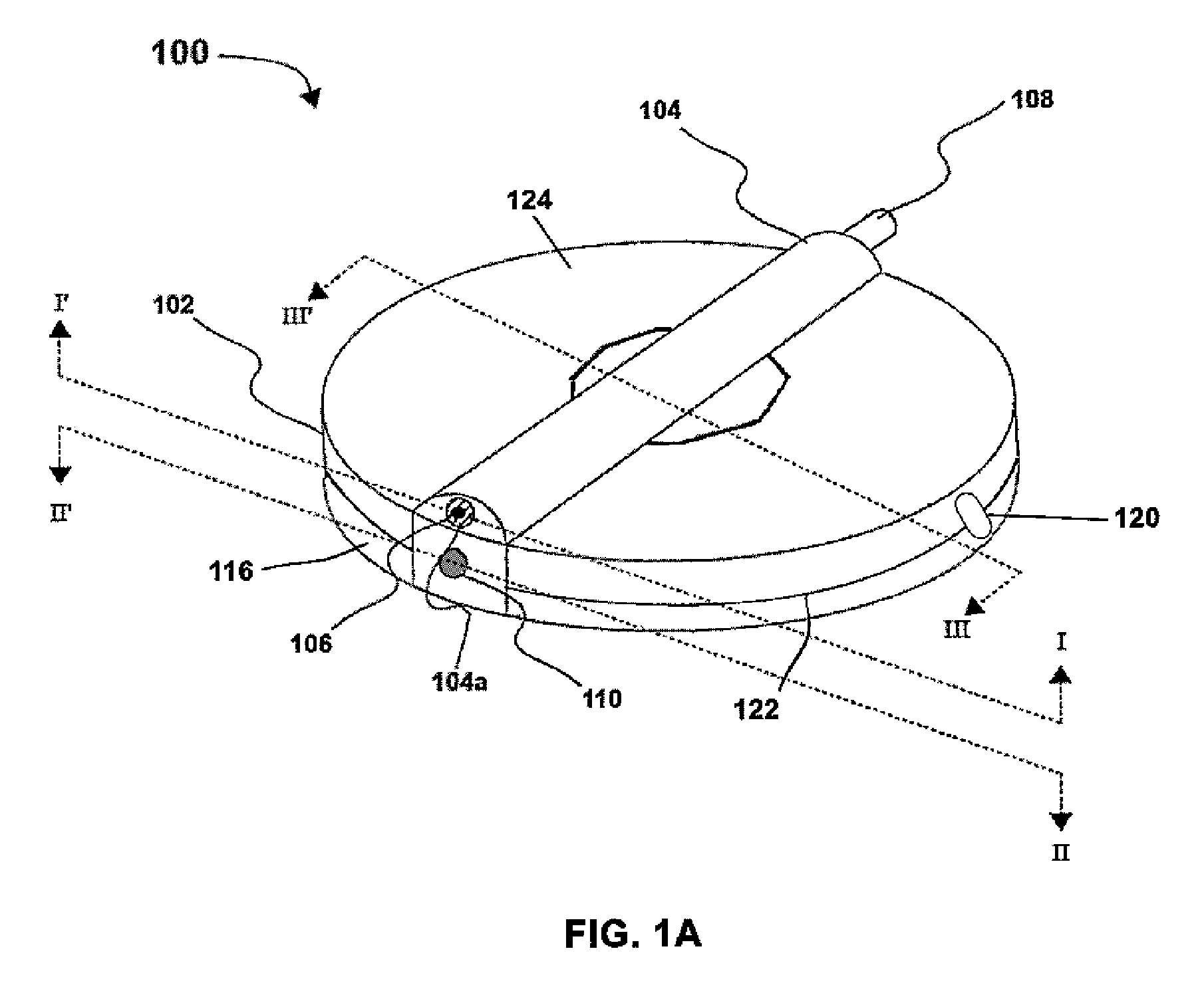
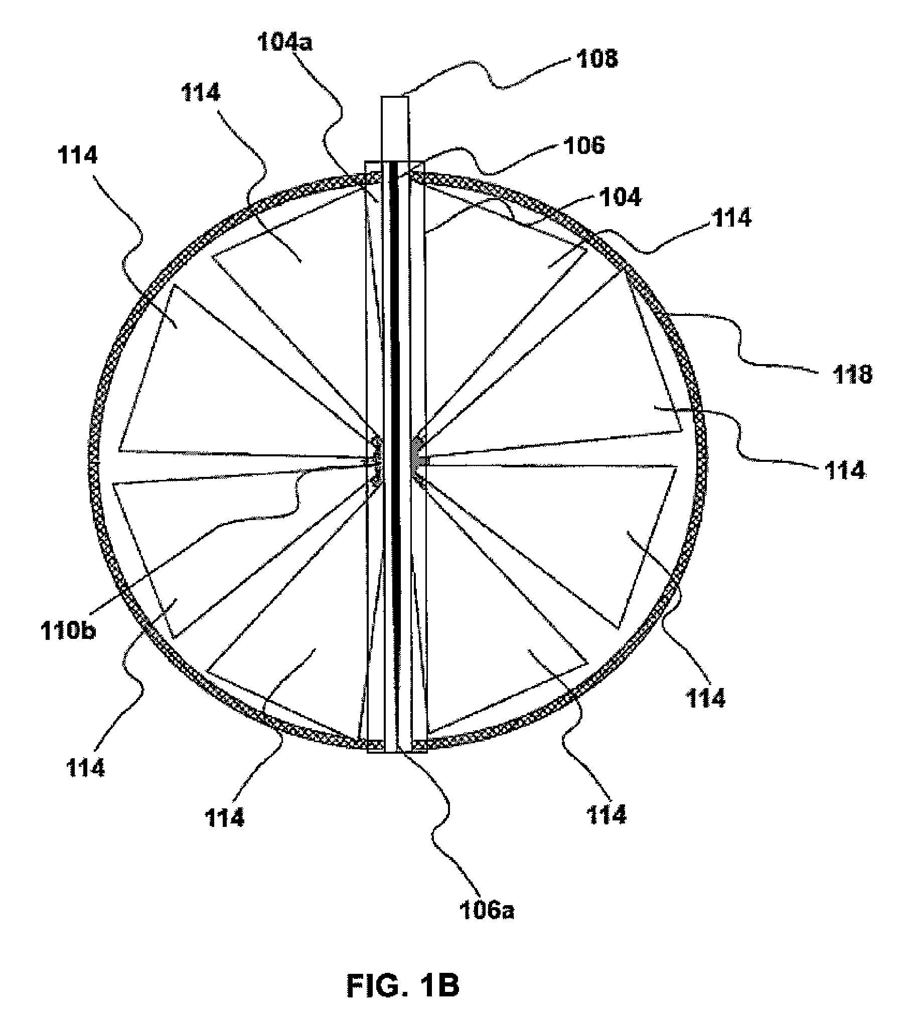
The present invention is a single-use device for collecting and storing body fluid samples as dried samples. It features a structural component that forms an interior chamber containing a sample collection material and a desiccant. The sample collection material is in fluid communication with a capillary tube or opening that extends to the exterior of the device. The device also has a detachable lancing mechanism for puncturing the skin. The invention provides for simplistic collection techniques, protection from contamination and ambient humidity, and ease of transport and sample stability at ambient temperature and humidity. It offers self-sampling by the patient in a remote location with no external reagent, equipment, or infrastructure requirements. The enclosed cartridge includes a drying agent in vaporous communication with the sampling material. Once the sample is drawn into the cartridge, it spreads out evenly on the filter paper where it is dried rapidly by the desiccant. The sample is then protected from contamination or ambient humidity and is ready for transport and / or storage. This significantly improves convenience for remote sampling.

Problems solved by technology

This is in contrast to current DBS methods that require a time-consuming manual hole punch for sample removal and potential distortion of results due to uneven analyte distribution across the diameter of the disc.d.

Method used


Image

  • Biological fluid sampling and storage apparatus for remote use
  • Biological fluid sampling and storage apparatus for remote use
  • Biological fluid sampling and storage apparatus for remote use

Examples


Embodiment Construction

[0030]As used herein, the term “capillary tube” refers to one or more narrow tubes of any length that moves a fluid at least partially through capillary action. The interior diameter of a tube is generally between about 0.5 and 5 mm in diameter, but may be larger or smaller depending on the nature of the sample to be collected, the physical composition of the tube, and any coating placed on the tube. The tube may also vary in diameter along its length, as by, for example, being wider or narrower at the “top” or “bottom.” One skilled in the art would be able to chose an optimal diameter and length for fluid transport with minimal experimentation. It is important to note herein that fluid may move through a “capillary tube” via other mechanisms as well, such as by gravity or by pressure differential, and that these mechanisms may be responsible for more motivational force than the capillary action within the capillary tube alone. It is intended that such tubes be included within our d...


PUM

PropertyMeasurementUnit
diameteraaaaaaaaaa
diameteraaaaaaaaaa
diameteraaaaaaaaaa

Abstract

An apparatus for sampling and storing biological fluids from a human or animal subject is provided. In one embodiment of the present disclosure, the apparatus includes a main body, lancet carrier or hub, lancet, lancet trigger, capillary tube, and sample compartments for collecting and storing dried blood and other bodily fluids. The lancet hub supports a lancet and provides for moving the lancet longitudinally between a first retracted position and a second extended position. The device includes a capillary tube having an internal diameter sized to draw and retain fluid from a contacted source using capillary action. The main body of the apparatus further includes a sample compartment for holding sampling and storage materials. In at least one embodiment of the present disclosure, the sample compartment can be accessed by lifting sample compartment lid. Also included is a new “fan” or “daisy” shaped collection material format for use in collecting and preserving samples.

Description

FIELD OF THE INVENTION[0001]The present invention generally relates to the collection and storage of blood and other biological fluids for subsequent testing. More particularly, the present invention is concerned with a method and apparatus for a single use collection of a body fluid and storage of a dried sample.BACKGROUND[0002]The current, most widely used procedure for diagnostic blood sample collection is venipuncture. This method generally requires a trained phlebotomist and sterile equipment including needles / lancets and collection tubes. The blood samples collected by venipuncture usually require separation by centrifugation and storage under refrigeration. An alternate method uses a lancet for skin piercing such as a finger stick. For example, U.S. Pat. No. 4,920,977 describes a blood collection assembly with lancet and microcollection tube, while U.S. Pat. No. 5,368,047, No. 4,654,513, and No. 5,320,607 each describe suction-type blood samplers. These devices develop suctio...

Claims


Application Information

Patent Timeline
Patent Type & Authority Patents(United States)
IPC IPC(8): G01N1/10A61B5/151A61B10/00
CPCG01N1/10A61B5/15142A61B10/0045A61B10/0096A61B5/15101A61B5/15144A61B10/0051A61B10/007A61B2010/0067A61B2010/0077A61B5/150022A61B5/150175A61B5/150786A61B5/150793A61B5/15113A61B5/15117Y10T436/25
Inventor HILL, JEANETTEHILL, JAMES
Owner SPOT BIOSCI LLC
Learn More