Eureka AIR delivers breakthrough ideas for toughest innovation challenges, trusted by R&D personnel around the world.

Laser processing method for workpiece

a technology of workpiece and laser, applied in the field of laser processing, can solve the problems of affecting the quality of workpiece, and the accuracy of alignment with each process line, so as to achieve the effect of suppressing the reduction in the strength of the workpiece, and ensuring the accuracy of alignmen

Active Publication Date: 2015-05-19
DISCO CORP
View PDF4 Cites 0 Cited by
  • Summary
  • Abstract
  • Description
  • Claims
  • Application Information

AI Technical Summary

Benefits of technology

[0006]It is therefore an object of the present invention to provide a laser processing method which can reduce the deviation of the laser applied position in applying a laser beam to the workpiece along each process line to perform laser processing to the workpiece.
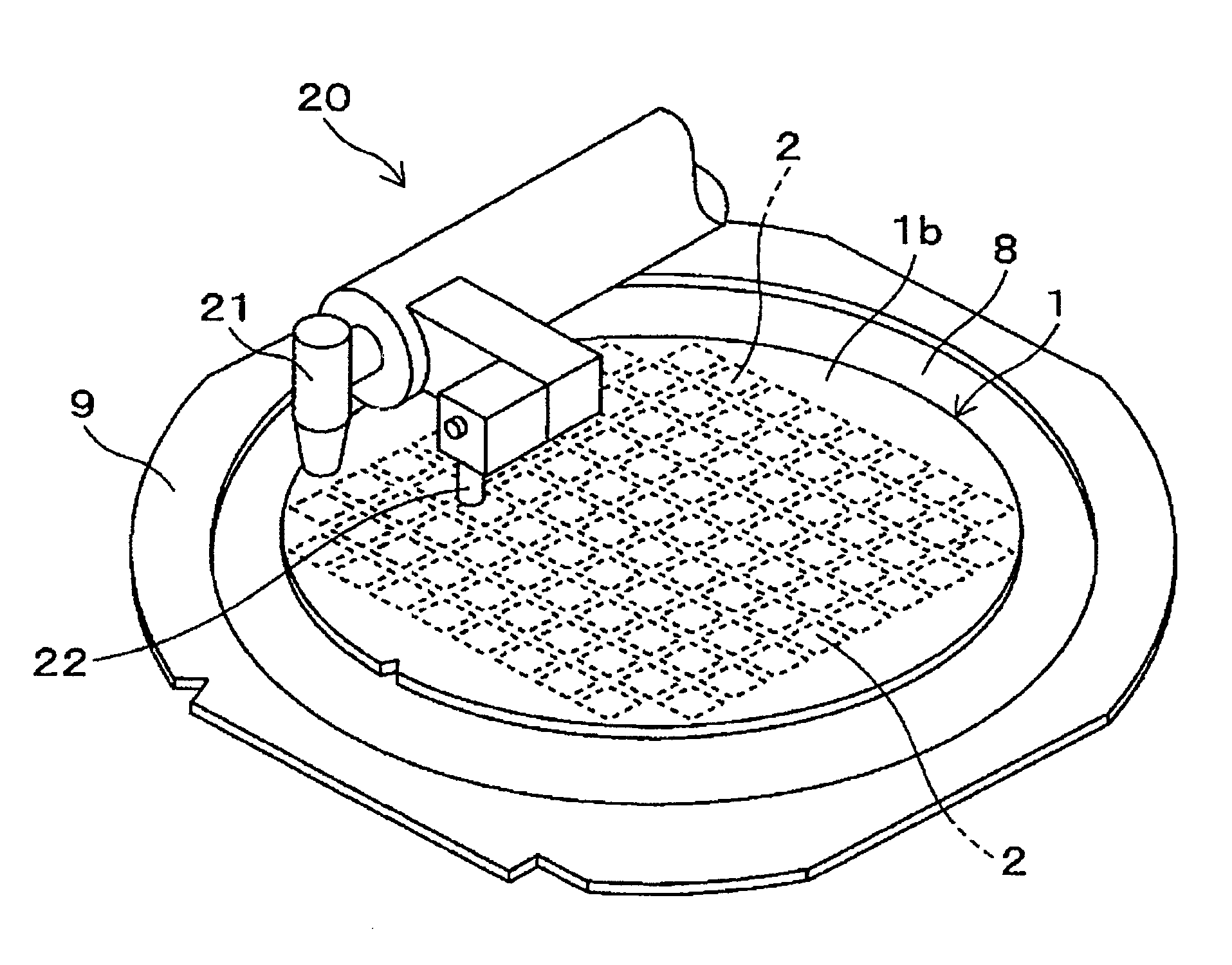
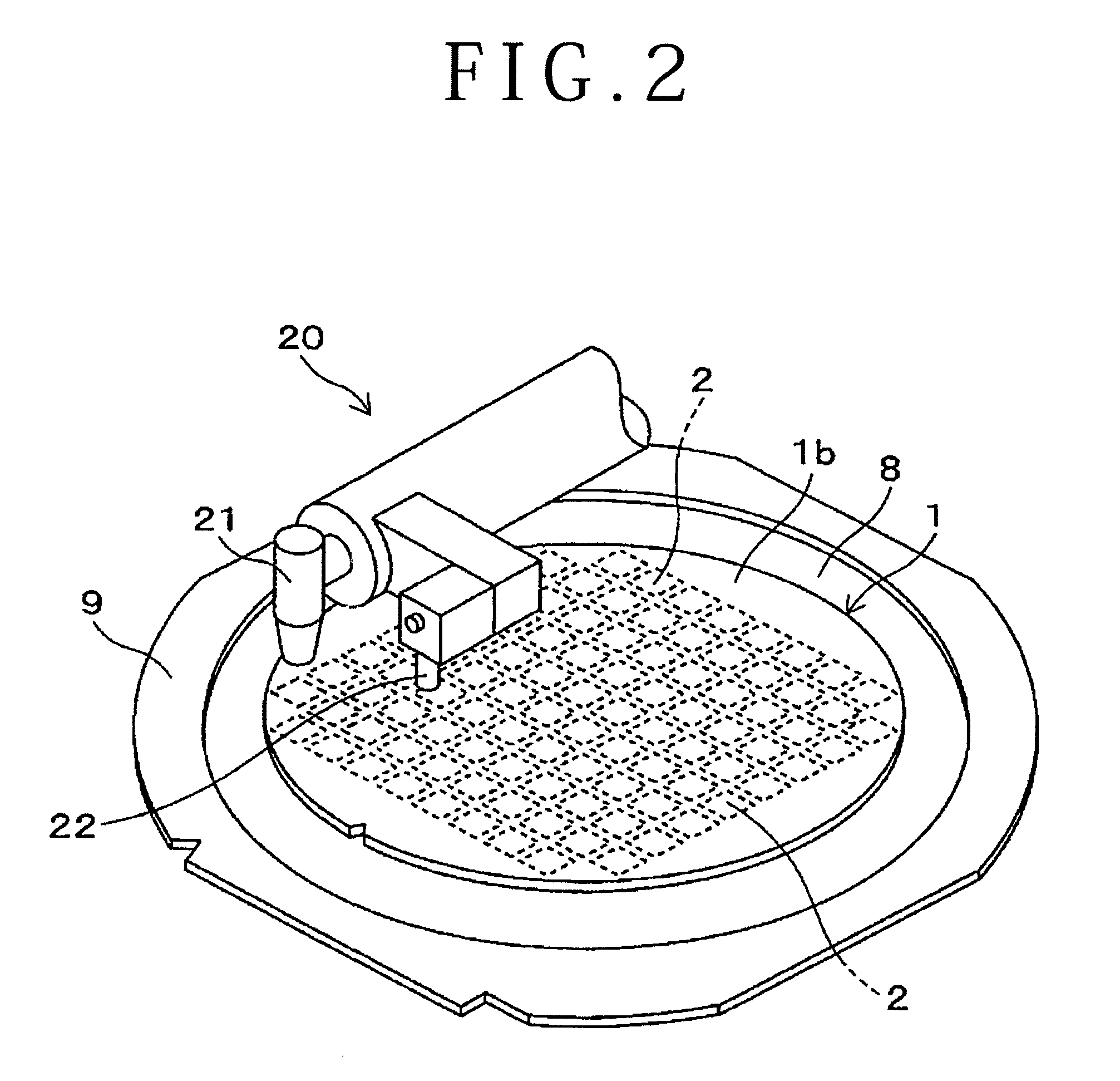
[0008]In the laser processing method of the present invention, the positional deviation correcting step is performed with predetermined timing during the performance of the laser processing step. That is, a positional deviation of a predetermined one of the modified layers already formed from the corresponding process line is detected to calculate a correction value according to the result of detection. Then, the correction value is added to data on applied position of the laser beam to make the applied position of the laser beam coincide with each process line after this correction. Accordingly, the deviation of the laser applied position can be reduced.
[0010]With this configuration, each correcting modified layer is formed as an index for detection of the positional deviation of each regular modified layer from the corresponding process line. Each correcting modified layer is formed at a vertical position near the back side of the workpiece above the corresponding regular modified layer. Accordingly, an image by electromagnetic waves reflected by each correcting modified layer can be obtained more clearly. As a result, the laser applied position can be aligned with each process line more accurately. Further, if each correcting modified layer is formed near the back side of the workpiece before forming the corresponding regular modified layer near the front side of the workpiece along the same process line, there is a possibility that the laser beam for forming the regular modified layer may be blocked by the correcting modified layer, so that the regular modified layer may not be formed. To the contrary, according to the present invention, the correcting modified layer is formed after forming the regular modified layer, so that the regular modified layer can be reliably formed.
[0011]Preferably, the correcting modified layer is locally formed so as to have a predetermined length along the corresponding process line. With this configuration, the correcting modified layer is locally formed, so that a reduction in strength of the workpiece can be suppressed.
[0012]Preferably, the predetermined height of each modified layer is greater than a finished thickness of the workpiece from the front side thereof; cracks are formed along each modified layer so as to extend from each modified layer to the front side of the workpiece; and the laser processing method further includes a grinding step of grinding the back side of the workpiece to reduce the thickness of the workpiece to the finished thickness after performing the laser processing step, thereby dividing the workpiece along each process line to obtain individual chips. By performing the grinding step, all of the correcting modified layers and all of the regular modified layers are removed, so that these modified layers are not left on each chip. As a result, the die strength of each chip can be improved as compared with the case where the modified layers are left on each chip.
[0013]According to the present invention, it is possible to provide a laser processing method which can reduce the deviation of the laser applied position in applying a laser beam to the workpiece along each process line to perform laser processing to the workpiece.

Problems solved by technology

In performing this kind of laser processing by using laser beam applying means such as a laser head unit, the components of the laser beam applying means may be expanded or contracted by temperature changes, causing a possibility that a laser applied position may be deviated from a target position.
In dividing the workpiece along this modified layer by applying an external force in the above case, there arises a problem such that the workpiece is not properly divided to produce odd-shaped chips or damage the devices.

Method used


Image

  • Laser processing method for workpiece
  • Laser processing method for workpiece
  • Laser processing method for workpiece

Examples


Embodiment Construction

[0025]A preferred embodiment of the present invention will now be described with reference to the drawings.

(1) Wafer

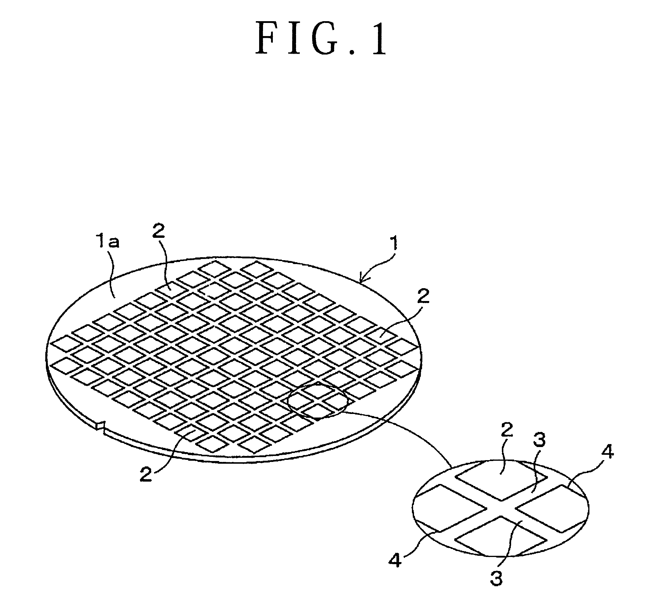
[0026]FIG. 1 shows a wafer 1 such as a semiconductor wafer as a workpiece in this preferred embodiment. The wafer 1 is formed of silicon or the like and it is a disk-shaped member having a thickness of about 700 μm, for example. A plurality of devices 2 are formed on a front side 1a of the wafer 1. A plurality of crossing division lines 3 (process lines) extending in a first direction and a second direction perpendicular to the first direction are formed on the front side 1a of the wafer 1 to thereby partition a plurality of rectangular regions 4 where a plurality of electronic circuits such as LSIs are respectively formed, thus forming the plural devices 2. This preferred embodiment is a laser processing method including the steps of laser processing and grinding the wafer 1 to thereby divide the wafer 1 into a plurality of rectangular regions 4 to obtain chips respec...


PUM

PropertyMeasurementUnit
thicknessaaaaaaaaaa
thicknessaaaaaaaaaa
thicknessaaaaaaaaaa

Abstract

During the performance of a laser processing step of applying a laser beam to a wafer to form modified layers inside the wafer respectively along division lines, a predetermined one of the modified layers already formed is imaged by a camera from the back side of the wafer with predetermined timing, and a positional deviation of the predetermined modified layer from the corresponding division line is detected to calculate a correction value. Then, the correction value is added to data on applied position of the laser beam to thereby make the applied position of the laser beam coincide with each division line. Accordingly, a positional deviation of the modified layer to be formed after this correction from each division line can be suppressed.

Description

BACKGROUND OF THE INVENTION[0001]1. Field of the Invention[0002]The present invention relates to a laser processing method of applying a laser beam to the inside of a thin platelike workpiece such as a semiconductor wafer from the back side thereof, thereby performing laser processing to the workpiece.[0003]2. Description of the Related Art[0004]In a semiconductor device fabrication process, a plurality of devices having electronic circuits are formed on the front side of a semiconductor wafer in a plurality of regions partitioned by a plurality of crossing division lines (process lines). The semiconductor wafer thus having the plural devices is divided along the division lines to thereby obtain a plurality of individual semiconductor chips respectively corresponding to the plural devices. As a method of dividing a workpiece such as a semiconductor wafer, there is a method including the steps of applying a laser beam having a transmission wavelength to the workpiece along each divis...

Claims


Application Information

Patent Timeline
Patent Type & Authority Patents(United States)
IPC IPC(8): H01L21/78B23K26/00B23K26/04B23K26/10B23K26/40
CPCH01L21/78B23K26/4075B23K26/0057B23K26/045B23K26/10B23K26/40B23K26/044B23K26/53B23K2103/50
Inventor OKADA, SHIGEFUMIOGOSHI, NOBUMORI
Owner DISCO CORP
Why Eureka
Eureka Blog
Learn More