
Methods of removing contaminants from hydrocarbon stream by swing adsorption and related apparatus and systems

a technology of hydrocarbon stream and contaminants, applied in the direction of separation process, gaseous fuel, fuel, etc., can solve the problems of not producing a viable solution to the problem of producing good recovery of methane, significant amount of product gas in the flow channel and void space, and poor recovery of desired produ

Active Publication Date: 2015-05-19
EXXONMOBIL UPSTREAM RES CO
View PDF261 Cites 47 Cited by
  • Summary
  • Abstract
  • Description
  • Claims
  • Application Information

AI Technical Summary

Benefits of technology

The present invention provides a swing adsorption process for removing contaminants, such as CO2, from hydrocarbon streams, such as natural gas streams. This process involves subjecting the natural gas stream to an adsorption step using a porous adsorbent material selective for CO2, which is then operated to remove CO2 and produce a gas product with reduced CO2 content. The process can be performed quickly, with multiple equalization and blow-down steps to ensure efficient removal of CO2 from the adsorbent bed before repressurization and reintroduction of the purified natural gas stream. The technical effect of this invention is to provide a rapid and effective means for removing CO2 from natural gas streams for purification and upgrading purposes.

Problems solved by technology

While there are various teachings in the art with respect to new adsorbent materials, new and improved parallel channel contactors, and improved rapid cycle PSA (RC-PSA) equipment, none of these to date present a viable solution to the problem of producing good recovery of methane when the feed gas is at high pressure.
This is a critical issue because natural gas is often produced at high pressures (30-700 bar) and it is preferred to operate the separation system at high pressure to avoid additional compression before transportation to the market.
One problem in extending PSA processes to high pressures, especially with those streams containing large amounts of CO2, is that at the end of the adsorption step there can be significant amounts of product gas in the flow channels and void spaces.
This can lead to poor recovery of the desired product and also to low purity product streams.
Conventional commercial practices for removal of acid gases from natural gas are limited in reaching high recovery and high purity, especially when acid gas concentrations are greater than 30%, because these processes involve considerable energy input in the form of refrigeration, and they often require sizable equipment.
These processes require handling and inventory storage for solvent as well as significant energy consumption for recovering the solvent.
For higher acid gas concentrations, some applications use bulk fractionation combined with technology like a Selexol physical solvent system which requires refrigeration and can result in extensive loss of heavy hydrocarbons to the acid gas stream.
Generally, simple PSA cycles can not take advantage of the kinetics of adsorption because the cycle times are long, and conventional PSA systems typically result in significant loss of methane with the acid gas stream.
The relatively low product recovery along with the large size and cost of conventional PSA systems typically prohibits their use in large-scale natural gas processing applications.
While various concepts have been proposed to enhance the performance of PSA systems, none have enabled separations at high pressure that provide the product purity and recovery required for natural gas processing.

Method used


Image

  • Methods of removing contaminants from hydrocarbon stream by swing adsorption and related apparatus and systems
  • Methods of removing contaminants from hydrocarbon stream by swing adsorption and related apparatus and systems
  • Methods of removing contaminants from hydrocarbon stream by swing adsorption and related apparatus and systems

Examples


example 1

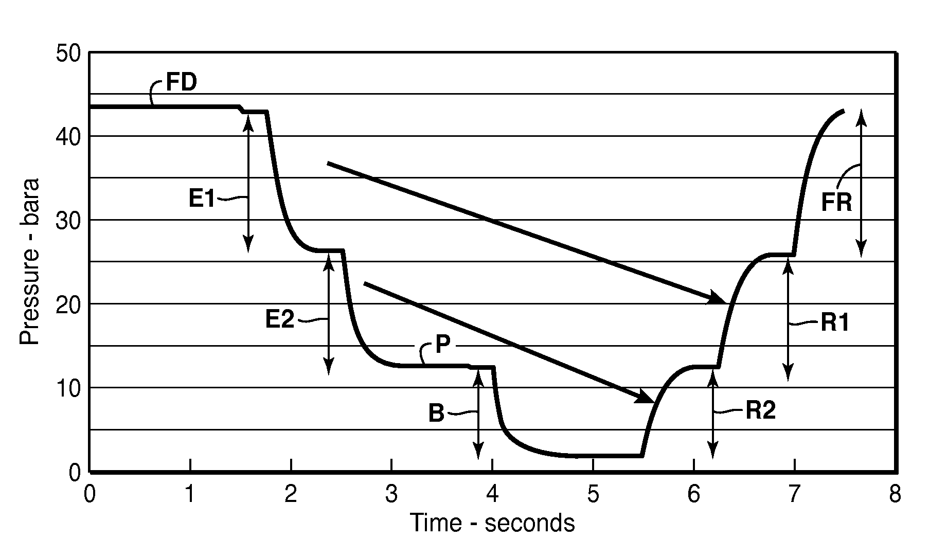
[0094]This example illustrates CO2 and H2S removal from natural gas at high-pressure using the RC-PSA system 700 from FIG. 7, wherein 98% recovery is predicted through simulation. With reference to the simplified process flow diagram in FIG. 7, the RC-PSA unit 701 is utilized along with various compressors 710a-710e to remove contaminants from a feed stream. The RC-PSA unit 701 includes multiple adsorbent beds connected via valves and piping as described in more detail below. To operate, the feed stream is passed to the RC-PSA unit 701 via conduit 702 and 704. The feed stream preferably comprises natural gas, which may be blended with the recycle stream from the recovery purge outlet conduit 703 associated with compressor 710a. A purified product stream rich in methane exits the RC-PSA unit 701 via conduit 706 at a slightly reduced pressure due to pressure drop across the adsorbent beds, valves and piping internal to the RC-PSA unit 701. In this example, the feed gas entering throug...

example 2

[0129]This example describes a modified cycle for the RC-PSA system in Example 1. In this example, the RC-PSA system 700 in FIG. 7 is used to process the same feed gas as described in Example 1. The configuration of each adsorbent bed is the same as Example 1, including flow channel dimensions, adsorbent bed length, adsorbent material, mesopore filler, etc. However, the number of adsorbent beds has increased from fourteen to sixteen to accommodate the modified cycle, which utilizes three equalization steps instead of two equalization steps as in Example 1.

[0130]A cycle schedule for the sixteen adsorbent beds for this example is shown in FIGS. 12a and 12b. Notation for the specific steps is the same as in FIGS. 10 and 11, described in Example 1. In FIGS. 12a and 12b, two groups of adsorbent beds are shown with the adsorbent beds in the first group labeled 1 to 8 in the top portion of the sequence graph and adsorbent beds in the second group labeled 9 to 16 in the bottom portion of th...

example 3

[0167]This example illustrates CO2 and H2S removal from natural gas at high-pressure using the RC-PSA system 800 from FIG. 8, wherein over 99% methane recovery is predicted and high purity product stream is produced with less than 1.5% CO2 and less than four ppm H2S. With reference to the simplified process flow diagram in FIG. 8, two RC-PSA units 801 and 821 are utilized along with various compressors 808 and 814 to remove contaminants from a feed stream. In this example, the two RC-PSA systems are arranged in series, where the first RC-PSA unit 801 produces the product gas of the required purity and the second RC-PSA unit 821 recovers methane from the blow-down stream of 801 to improve the overall product recovery for the system 800. Each of the two RC-PSA units 801 and 821 include one or more adsorption beds connected via valves and piping.

[0168]The natural gas feed stream containing CO2 and H2S enters the first RC-PSA unit 801 via conduit 802 and a purified product stream enrich...


PUM

PropertyMeasurementUnit
diametersaaaaaaaaaa
diametersaaaaaaaaaa
adsorption timeaaaaaaaaaa

Abstract

A pressure swing adsorption process for removal of CO2 from natural gas streams through a combination of a selective adsorbent material containing an effective amount of a non-adsorbent filler, adsorbent contactor design, and adsorption cycle design. The removal of contaminants from gas streams, preferably natural gas streams, using rapid-cycle swing adsorption processes, such as rapid-cycle pressure swing adsorption (RC-PSA). Separations at high pressure with high product recovery and / or high product purity are provided through a combination of judicious choices of adsorbent material, gas-solid contactor, system configuration, and cycle designs. For example, cycle designs that include steps of purge and staged blow-down as well as the inclusion of a mesopore filler in the adsorbent material significantly improves product (e.g., methane) recovery. An RC-PSA product with less than 10 ppm H2S can be produced from a natural gas feed stream that contains less than 1 mole percent H2S.

Description

CROSS REFERENCE TO RELATED APPLICATIONS[0001]This application is the National Stage entry under 35 U.S.C. 371 of PCT / US2012 / 026801 that published as Intl. Patent App. Pub. No. 2012 / 118758 and was filed on 27 Feb. 2012, which claims the benefit of U.S. Patent Application No. 61 / 448,121 entitled METHODS OF REMOVING CONTAMINANTS FROM A HYDROCARBON STREAM BY SWING ADSORPTION AND RELATED APPARATUS AND SYSTEMS, filed on 1 Mar. 2011, each of which is incorporated by reference, in its entirety, for all purposes.[0002]This application is related to U.S. Patent Application No. 61 / 448,117 entitled APPARATUS AND SYSTEMS HAVING AN ENCASED ADSORBENT CONTACTOR AND SWING ADSORPTION PROCESSES RELATED THERETO, filed Mar. 1, 2011; U.S. Patent Application No. 61 / 448,120 entitled APPARATUS AND SYSTEMS HAVING A RECIPROCATING VALVE HEAD ASSEMBLY AND SWING ADSORPTION PROCESSES RELATED THERETO, filed Mar. 1, 2011; U.S. Patent Application No. 61 / 448,123 entitled APPARATUS AND SYSTEMS HAVING A ROTARY VALVE AS...

Claims


Application Information

Patent Timeline
Patent Type & Authority Patents(United States)
IPC IPC(8): B01D53/047B01D53/02C10L3/10
CPCB01D53/047B01D53/0473C10L3/104B01D53/02B01D2256/245B01D2257/304B01D2257/502B01D2259/40041B01D2259/40049B01D2259/4063Y02C10/08Y02C20/40
Inventor DECKMAN, HARRY W.JOHNSON, ROBERT A.KELLEY, BRUCE T.RAVIKOVITCH, PETER I.ANDERSON, THOMAS N.
Owner EXXONMOBIL UPSTREAM RES CO
Learn More