
System for discretely actuated solar mirrors

a solar mirror and discrete technology, applied in the field of mirror system establishing, can solve the problems of inability to construct a single mirror system, inability to manufacture high cost of manufacturing precision mirrors for solar concentrators, so as to achieve a simple method of controlling the shap

Active Publication Date: 2015-04-28
MASSACHUSETTS INST OF TECH
View PDF16 Cites 4 Cited by
  • Summary
  • Abstract
  • Description
  • Claims
  • Application Information

AI Technical Summary

Benefits of technology

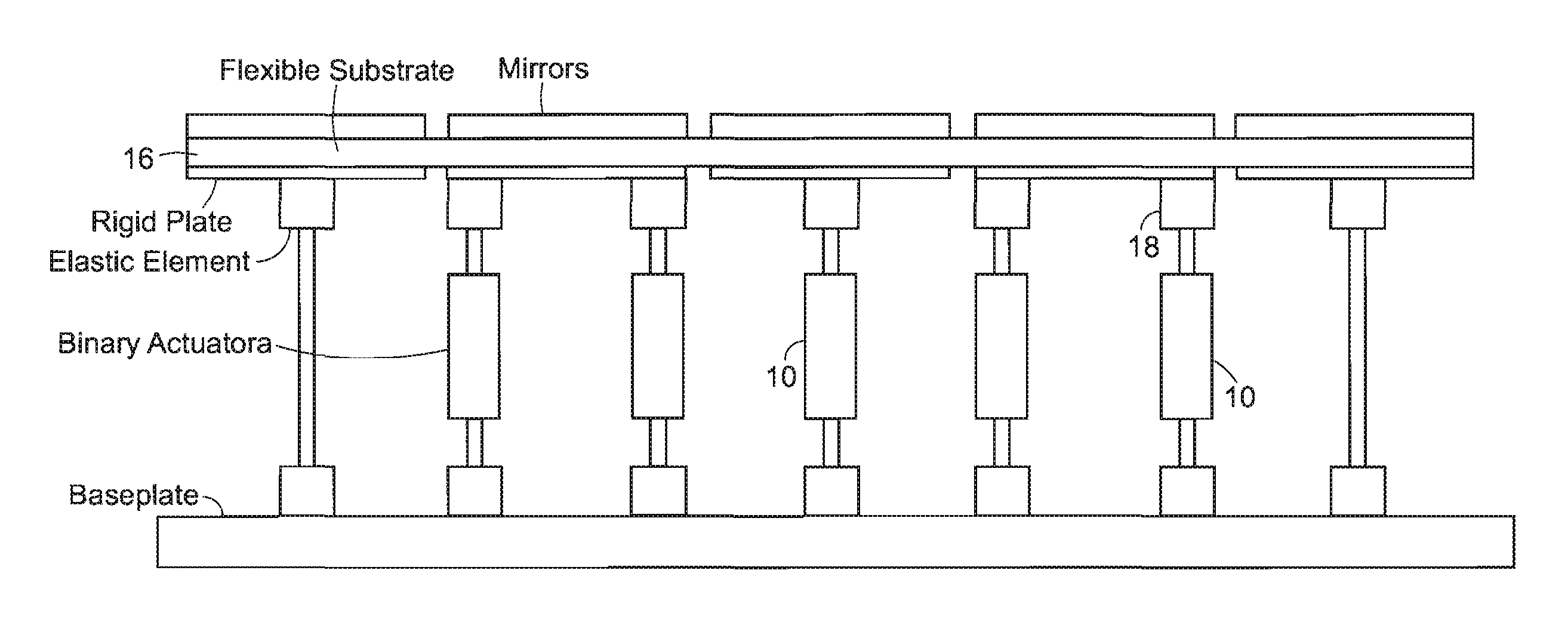
[0013]The invention disclosed herein provides a simpler method of controlling the shape and position of solar mirrors. In an embodiment of this approach, binary actuators are embedded in a compliant mirror substructure, and the actuators are deployed in a specified pattern to correct mirror shape.

Problems solved by technology

Constructing these systems from a single mirror is not practical because of their large size.
Segmented mirror telescopes such as the James Webb Telescope often have errors in their composite shape due to construction tolerances in the mirror supporting structure and disturbances such as thermal distortions, gravity, etc.
Manufacturing precision mirrors for solar concentrators and making them robust to disturbances such as wind and thermal warping is expensive.
Imprecision in mirror shape due to manufacturing limitations and disturbances degrades the performance of solar concentrator systems [2-4].
Using embedded actuators to actively control a structure's shape is complex and has been a topic of research.
First, systems containing continuous actuators are complex and require a large number of actuators, sensors and motion control systems.
Further, these continuous actuators are heavy, a major issue for space systems.
In addition, these systems have a high probability of failure.
The hostile environments in which solar mirrors are used (space, deserts and seaside regions) degrade precision motion control elements and repairs are often difficult or impossible due to restricted access.

Method used


Image

  • System for discretely actuated solar mirrors
  • System for discretely actuated solar mirrors
  • System for discretely actuated solar mirrors

Examples


Embodiment Construction

[0021]Throughout the specification, whenever the term “mirror” is used it is noted that other elements such as photovoltaic collectors or thermal solar concentrator elements are intended as well.

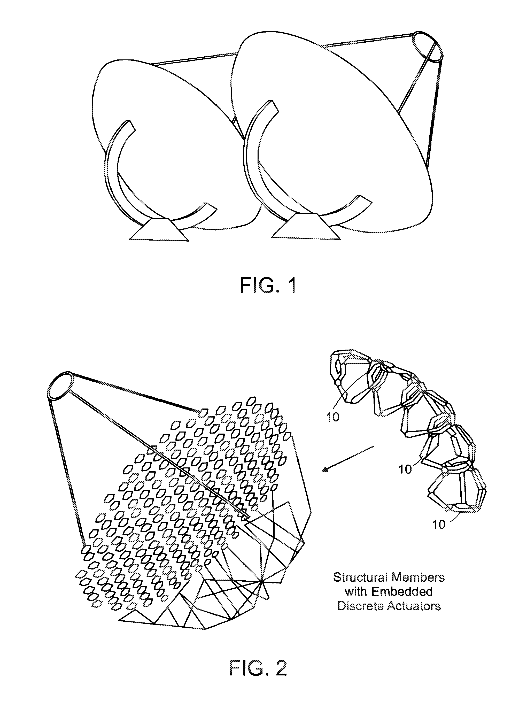
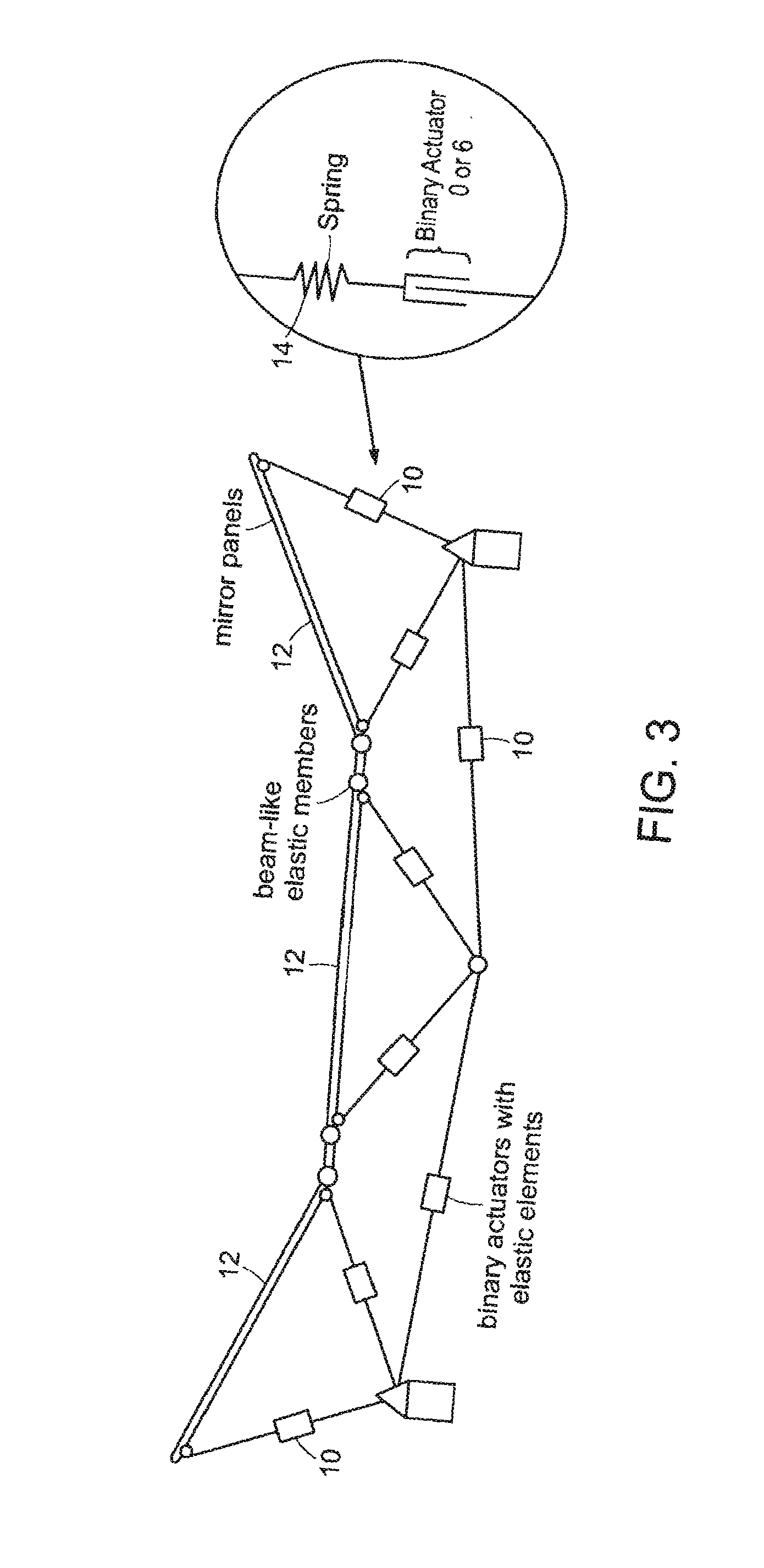
[0022]A mirror is usually mounted on a supporting structure that might contain hinges and elastic elements. Also contained in or mounted to the structure are actuators that can assume a multiplicity of stable positions of elongation. Power is not necessary to maintain each actuator in its stable positions. In a preferred embodiment these actuators are binary, but multi-stable configurations with larger numbers of states are also contemplated. One implementation of an embodiment of the invention is shown in FIG. 2. The discrete actuators 10 may be based on simple binary dielectric elastic actuators [12], lead screws, pneumatic or hydraulic cylinders, electromagnetic solenoids or other devices.

[0023]In one of the implementations of the invention, the binary actuators 10 may be mounted to mecha...


PUM


Abstract

System for establishing a surface shape. The system includes a compliant substrate including the surface and having a reverse side, and a plurality of discrete actuators engaging the reverse side and arranged in a selected pattern to control the surface shape as individual discrete activators are activated. It is preferred that the actuators have multiple discrete stable states of elongation. A particularly preferred embodiment uses actuators that are binary with two stable states of elongation.

Description

BACKGROUND OF THE INVENTION[0001]This invention relates to a system for establishing the shape of mirrors for solar collectors, and more particularly to such a system that uses discrete actuators.[0002]Very large mirrors and optical arrays are used in a number of applications. These applications include in-orbit large space telescopes for astronomical imaging and scientific earth observation systems. Large mirrors and optical arrays may be used in terrestrial systems as well, such as large and small solar energy concentrators. These systems often consist of precision manufactured segmented mirrors and panels as seen in FIG. 1. Constructing these systems from a single mirror is not practical because of their large size.[0003]One example of an in-orbit telescope is the James Webb Telescope now being designed and built by NASA [1]. Numerals in brackets refer to the references included herewith. The contents of all of the references cited herein are incorporated herein by reference in t...

Claims


Application Information

Patent Timeline
Patent Type & Authority Patents(United States)
IPC IPC(8): G02B5/08F24J2/08G02B7/182F24S23/30F24S23/70G02B7/183G02B26/08
CPCG02B26/0825G02B7/183F24J2002/1004F24J2002/1085F24S2023/83F24S2023/874
Inventor DUBOWSKY, STEVENBILTON, AMY M.LEE, SEUNG J.
Owner MASSACHUSETTS INST OF TECH
Learn More