
Image heating apparatus

a heating apparatus and image technology, applied in the field of image heating apparatus, can solve the problems of the thermal capacity of the fixing roller, and achieve the effects of shortening the fpot, reducing the thermal capacity of the fixing roller, and reducing the temperature rise of the non-sheet-passing portion of the fixing roller

Active Publication Date: 2015-04-21
CANON KK
View PDF24 Cites 4 Cited by
  • Summary
  • Abstract
  • Description
  • Claims
  • Application Information

AI Technical Summary

Benefits of technology

The present invention aims to improve image heating in a fixing roller by reducing its thermal capacity, thereby minimizing non-sheet-passing portion temperature rise and decreasing the time required for the sheet to achieve the desired temperature.

Problems solved by technology

However, in the conventional fixing roller of the heating roller type including the elastic layer, the thermal capacity of the fixing roller is large, and therefore the fixing roller surface is increased in temperature to a predetermined temperature by heat transfer from an inner surface of the fixing roller via the elastic layer having a large thickness.

Method used


Image

  • Image heating apparatus
  • Image heating apparatus
  • Image heating apparatus

Examples


embodiment 1

(Embodiment 1)

[0021]A first exemplary embodiment is described.

(1) Image Forming Portion

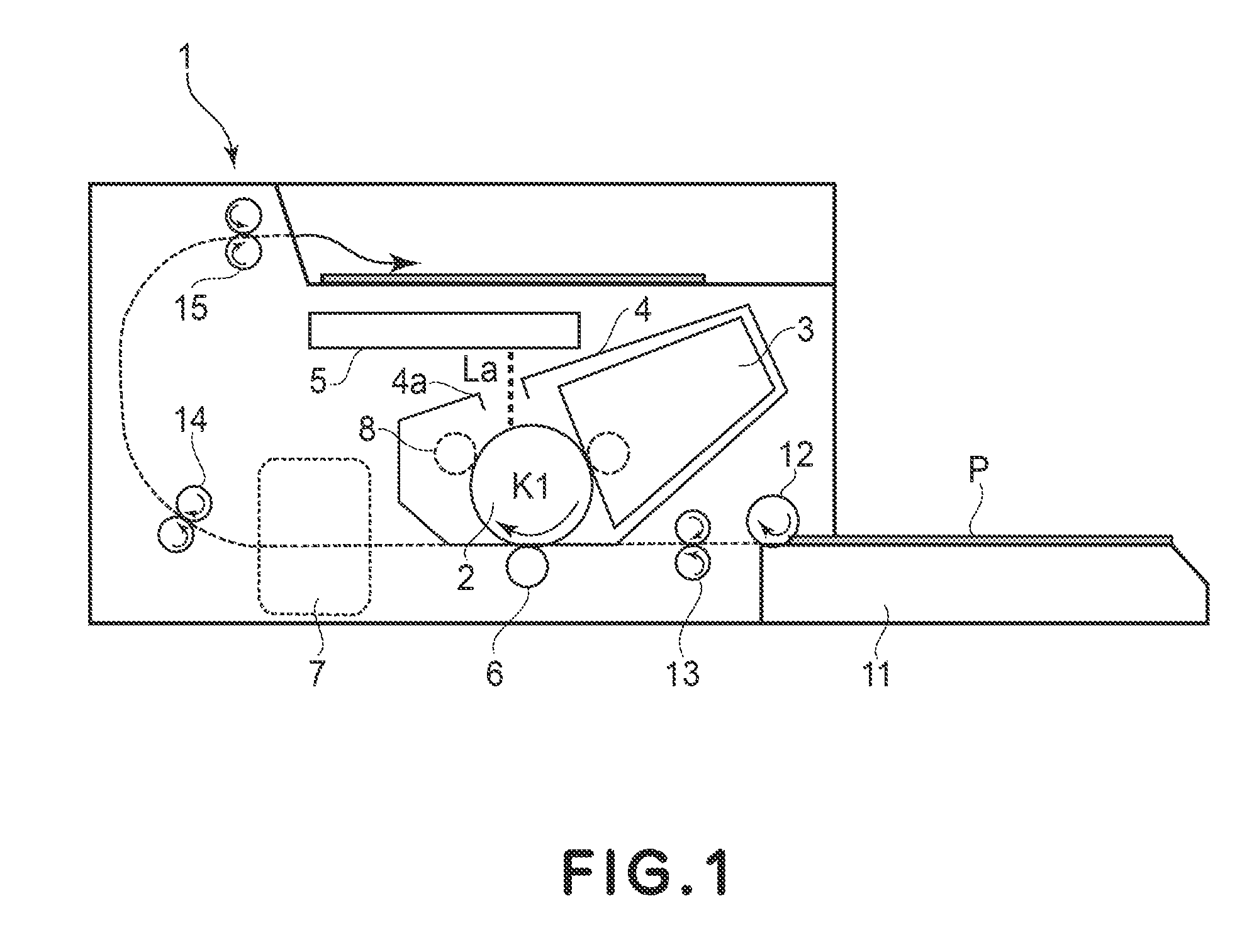
[0022]FIG. 1 is a sectional view showing a schematic structure of an example of an image forming apparatus 1 in which an image heating apparatus according to the present invention is mounted as a fixing device 7. This apparatus 1 is a laser beam printer of an electrophotographic type. Into the printer 1, image information is inputted from an image information providing device (external host device) such as a host computer or the like provided outside the printer 1. Further, the printer 1 performs, by an electrophotographic method, a series of image forming processes such that an image depending on the inputted image information is formed and recording on a sheet-like recording material P.

[0023]The printer 1 includes a process cartridge 4 in which a drum-like rotatable electrophotographic photosensitive member 2 as an image bearing member, a primary charging mechanism 8 and a developing device 3 ar...

embodiment 2

[Embodiment 2]

[0112]A second exemplary embodiment is described.

[0113]FIG. 9 is a cross-sectional view showing a schematic structure of a fixing device 7 in Embodiment 2. In this embodiment, the fixing device 7 is characterized by using an induction heating member (magnetic field generating member) as an external heating member 21A for a fixing roller 30.

[0114]In the fixing device 7 in this embodiment, the roller 30 is prepared by replacing the high heat transfer layer 33 of the roller 30 in the fixing device in Embodiment 1 with a metal sleeve 33A having an electromagnetic induction heat generating property. The sleeve 33A is, as described later, subjected to induction heating by the action of a magnetic field by the magnetic field generating member 21A provided in non-contact to and opposed to the outer peripheral surface of the roller 30.

[0115]The material for the sleeve 33A comprises an electroconductive member having a magnetic property such that it is capable of generating heat...


PUM


Abstract

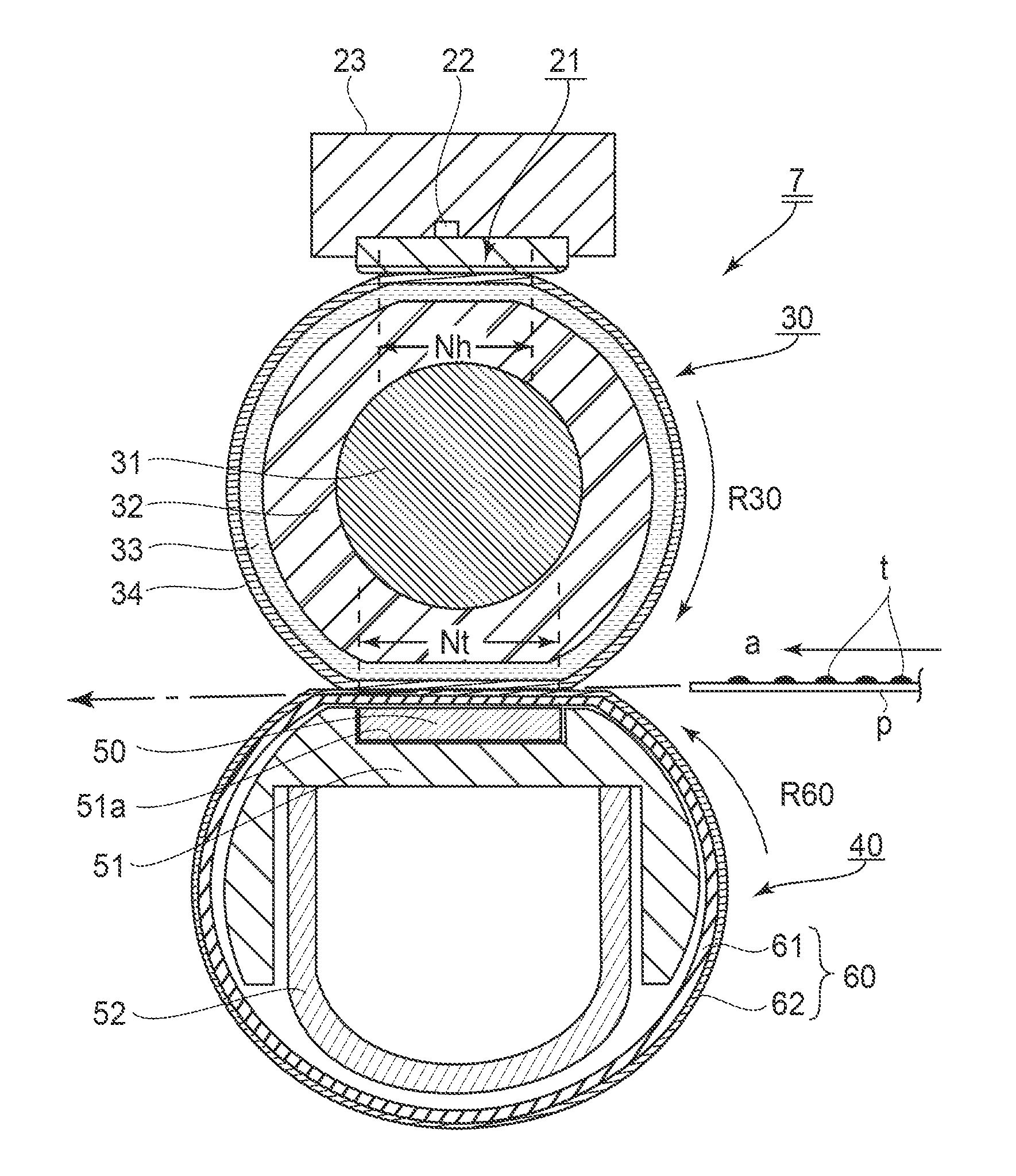
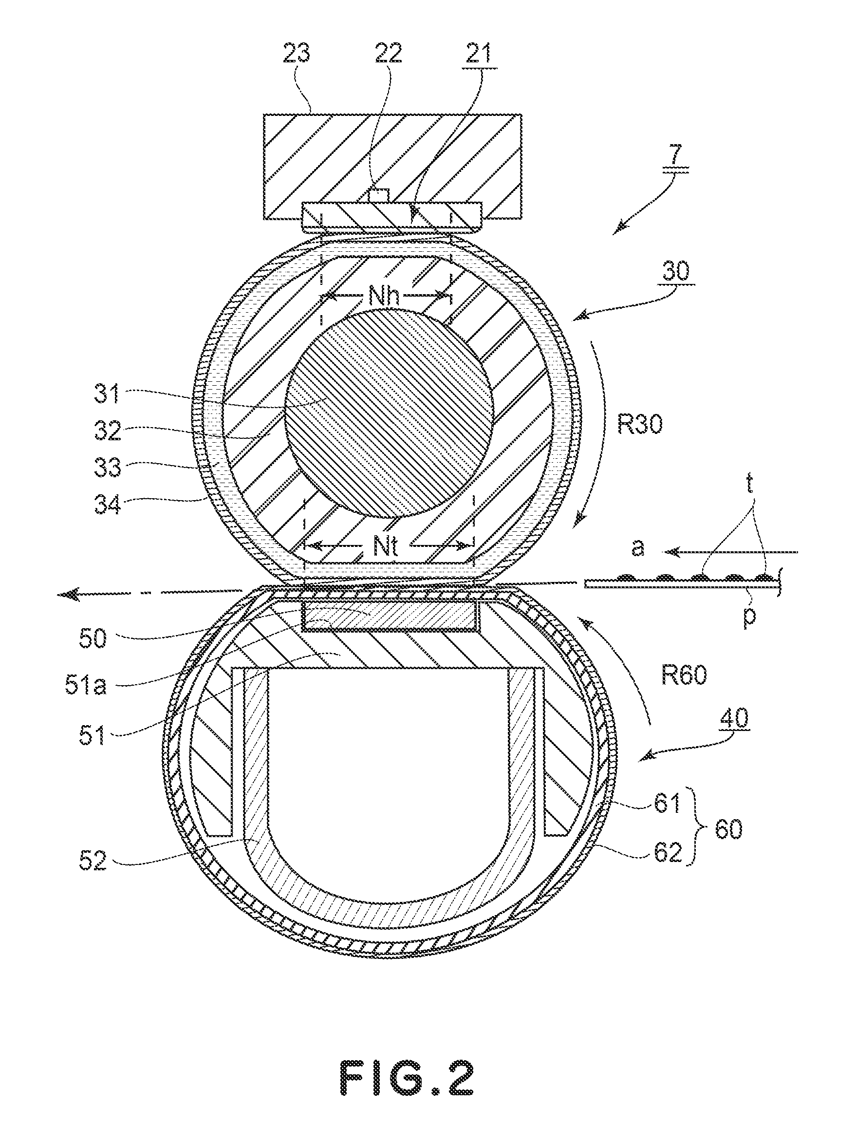
An image heating apparatus for heating a recording material, on which a toner image is carried, while conveying the recording material in a nip includes: a fixing roller including a metal core, a heat insulating layer formed on a surface of the core metal, and a high heat transfer layer which is formed on an outer peripheral surface of the heat insulating layer and has a higher thermal conductivity than the heat insulating layer; a heating member for heating the fixing roller from an outside; and a back-up member for forming the nip together with the fixing roller. When the fixing roller and the back-up member opposing the fixing roller are supplied with the same heat quantity, the temperature rise rate in a neighborhood of the surface of the back-up member supplied with the heat quantity is higher than that of the fixing roller.

Description

FIELD OF THE INVENTION AND RELATED ART[0001]The present invention relates to an image heating apparatus suitably used as an image fixing device (apparatus) mounted in an image forming apparatus such as an electrophotographic copying machine or an electrophotographic laser beam printer, and relates to the image forming apparatus in which the image heating apparatus is mounted.[0002]As the image heating apparatus, a fixing device for heat-fixing an unfixed image, as a fixed image, formed on a actually measured and a glossiness increasing device (image modifying device) for increasing glossiness of an image, fixed on the recording material, by re-heating the image are cited.[0003]As the image heating apparatus (fixing device) used in equipment, using an electrophotographic process, such as the electrophotographic copying machine, a facsimile machine or a printer, those of a heating roller type has been conventionally used in general. The fixing device of the heating roller type include...

Claims


Application Information

Patent Timeline
Patent Type & Authority Patents(United States)
IPC IPC(8): G03G15/20
CPCG03G15/2042G03G15/2057G03G15/206G03G15/2064G03G2215/2025G03G2215/2051
Inventor OKAYASU, KOHEINISHIDA, SATOSHI
Owner CANON KK
Learn More