
Automatic clock tree routing rule generation

a clock tree and automatic technology, applied in the field of automatic clock tree routing rule generation, can solve problems such as considerably more challenging circuit design

Active Publication Date: 2015-04-14
SYNOPSYS INC
View PDF13 Cites 14 Cited by
  • Summary
  • Abstract
  • Description
  • Claims
  • Application Information

AI Technical Summary

Benefits of technology

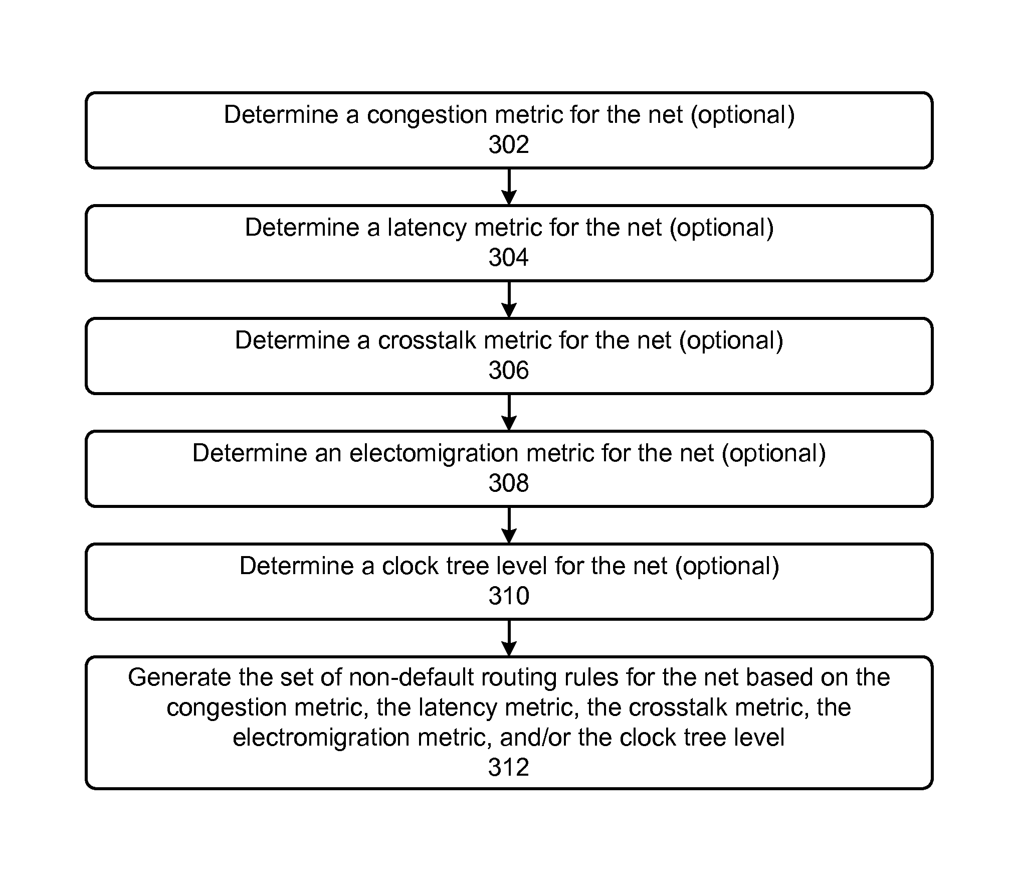
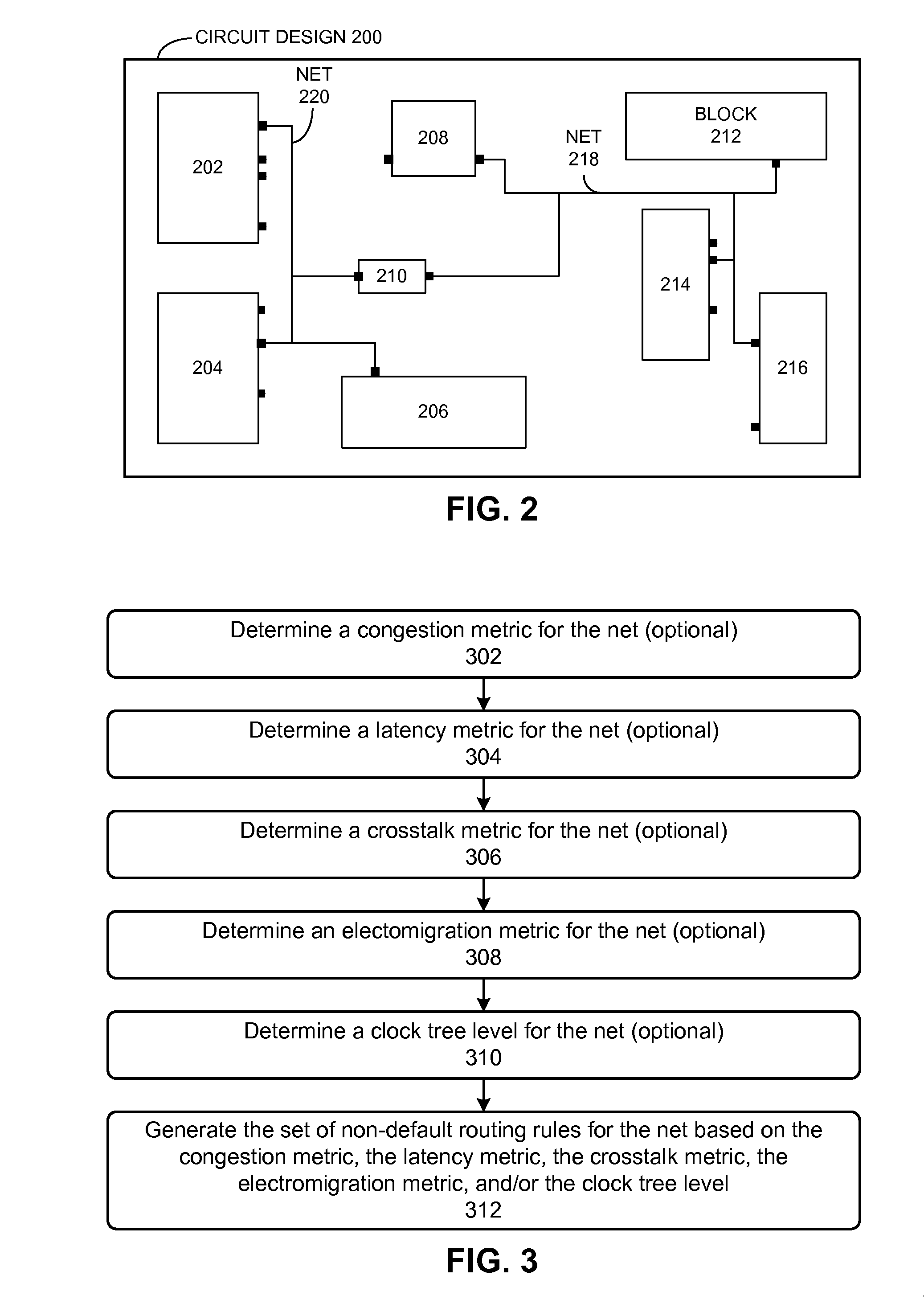
[0008]Next, the embodiments can generate the set of non-default routing rules for routing the net based on one or more metrics. A routing rule can specify how wide the wires are supposed to be and how far apart adjacent wires are to be placed. A non-default routing rule can specify a wire width that is different from the default width and / or specify a spacing (i.e., the distance between two wires) that is different from the default spacing. Specifically, in response to determining that the congestion metric indicates that the net is in a high congestion region, some embodiments can generate a routing rule that uses a default rule wire width, a default rule spacing, or both. On the other hand, in response to determining that the congestion metric indicates that the net is not in a high congestion region, some embodiments can generate one or more of the following routing rules: (1) a routing rule that uses a wire width that is wider than a default rule wire width, a spacing that is wider than a default rule spacing, or both, (2) a routing rule that uses a wire width and / or a spacing that prevents the net from violating a clock latency rule, (3) a routing rule that uses a wire width and / or a spacing that prevents the net from violating a crosstalk rule, (4) a routing rule that uses a wire width and / or a spacing that prevents the net from violating an electromigration rule, and / or (5) a routing rule that uses a width value and a spacing value based on the clock tree level, wherein greater width and spacing values are used at higher clock tree levels.

Problems solved by technology

This dramatic increase in semiconductor integration densities has made it considerably more challenging to design circuits.

Method used


Image

  • Automatic clock tree routing rule generation
  • Automatic clock tree routing rule generation
  • Automatic clock tree routing rule generation

Examples


Embodiment Construction

[0013]The following description is presented to enable any person skilled in the art to make and use the invention, and is provided in the context of a particular application and its requirements. Various modifications to the disclosed embodiments will be readily apparent to those skilled in the art, and the general principles defined herein may be applied to other embodiments and applications without departing from the spirit and scope of the present invention. Thus, the present invention is not limited to the embodiments shown, but is to be accorded the widest scope consistent with the principles and features disclosed herein. In this disclosure, when the term “and / or” is used with a list of entities, it refers to all possible combinations of the list of entities. For example, the phrase “X, Y, and / or Z” covers the following cases: (1) only X; (2) only Y; (3) only Z; (4) X and Y; (5) X and Z; (6) Y and Z; and (7) X, Y, and Z. Additionally, in this disclosure, the term “based on” m...


PUM


Abstract

Systems and techniques are described for automatically generating a set of non-default routing rules for routing a net in a clock tree based on one or more metrics. The metrics can include a congestion metric, a latency metric, a crosstalk metric, an electromigration metric, and a clock tree level. Next, the embodiments can generate the set of non-default routing rules for routing the net based on one or more metrics. A routing rule can specify how wide the wires are supposed to be and how far apart adjacent wires are to be placed. A non-default routing rule can specify a wire width that is different from the default width and / or specify a spacing (i.e., the distance between two wires) that is different from the default spacing.

Description

RELATED APPLICATION[0001]This application claims priority to U.S. Provisional Patent Application No. 61 / 746,065, entitled “Automatic clock tree routing rule generation,” by the same inventors, and was filed on 26 Dec. 2012, the contents of which are herein incorporated by reference in their entirety for all purposes.BACKGROUND[0002]1. Technical Field[0003]This disclosure relates to clock tree synthesis during electronic circuit design. More specifically, this disclosure relates to automatic clock tree routing rule generation.[0004]2. Related Art[0005]Advances in semiconductor technology presently make it possible to integrate hundreds of millions of transistors onto a single semiconductor chip. This dramatic increase in semiconductor integration densities has made it considerably more challenging to design circuits.[0006]Clock tree synthesis (CTS) and routing are two important operations in electronic design automation (EDA). CTS refers to the process of creating a clock distributio...

Claims


Application Information

Patent Timeline
Patent Type & Authority Patents(United States)
IPC IPC(8): G06F17/50
CPCG06F17/5077G06F30/396G06F30/394
Inventor CAO, AIQUNDHAR, SANJAYYUAN, LIN
Owner SYNOPSYS INC
Learn More