Eureka AIR delivers breakthrough ideas for toughest innovation challenges, trusted by R&D personnel around the world.

Hemostasis valve device

a valve and valve body technology, applied in the direction of intravenous devices, trocars, other medical devices, etc., can solve the problems of inconvenient use of valves, easy leakage, blood flowing backwards

Inactive Publication Date: 2015-04-14
HUBIOMED INC
View PDF10 Cites 34 Cited by
  • Summary
  • Abstract
  • Description
  • Claims
  • Application Information

AI Technical Summary

Benefits of technology

[0012]The present invention is applied to solve the disadvantages of the prior art, and an objective of the present invention is to provide a new hemostasis valve device which allows a tube, a guide wire, or a catheter to be inserted into the left or right coronary artery via the femoral artery or an arm artery at the time of a Cardiac Catheterization or Percutaneous Transluminal Coronary Angioplasty operation, wherein sealing members mounted in two independent positions are opened and closed by means of press and release actions of push buttons coupled to the outside of a fastening tube as well as the rotation of the fastening tube, respectively, so that the leakage of blood or the inflow of outside air is simply and effectively shut off during the surgical operation.
[0013]Another objective of the present invention is to provide a new hemostasis valve device in which a drug influx tube for allowing a medicine such as a thrombolitic drug to flow into a patient during the Cardiac Catheterization or PTCA operation pivots and is adjusted in a stepwise manner within a certain range of angles on a basis of body conditions or movements of the patient, so that the convenience of the surgical operation is more improved.

Problems solved by technology

However, the medical fluid flow control valve of the prior art has disadvantages that the valve is inconveniently used because being configured in such a way that the sealing unit is compressed and decompressed according to the rotational movement of the cap, blood flowing backward during a surgical operation may easily leak because the sealing unit is mounted in one position, and improper outside air may flow into a blood vessel at the insertion of a tube, a guide wire, or a catheter (hereinafter, the tube, guide wire, and catheter are referred to as “different catheters”), which causes air embolism.
In addition, the valve of the prior art has another disadvantage that is inconveniently used because a drug influx tube for allowing a medicine such as a thrombolitic drug to be injected into a blood vessel as necessary during the surgical operation may not be variably adjusted on a basis of body conditions or movements of a patient and is fixedly formed outside an insertion tube configuring the control valve.

Method used


Image

  • Hemostasis valve device
  • Hemostasis valve device
  • Hemostasis valve device

Examples


Embodiment Construction

[0022]Hereinafter, a preferred embodiment of the present invention is described in more detail with reference to the accompanying drawings.

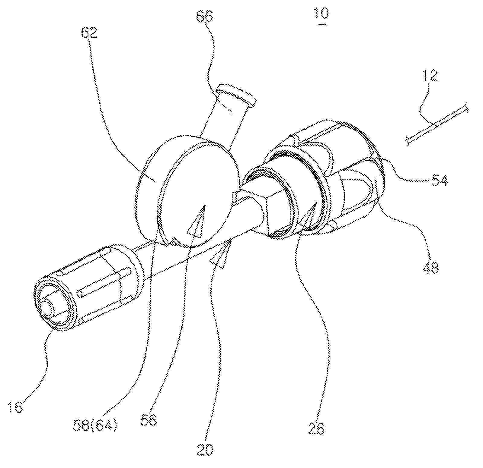
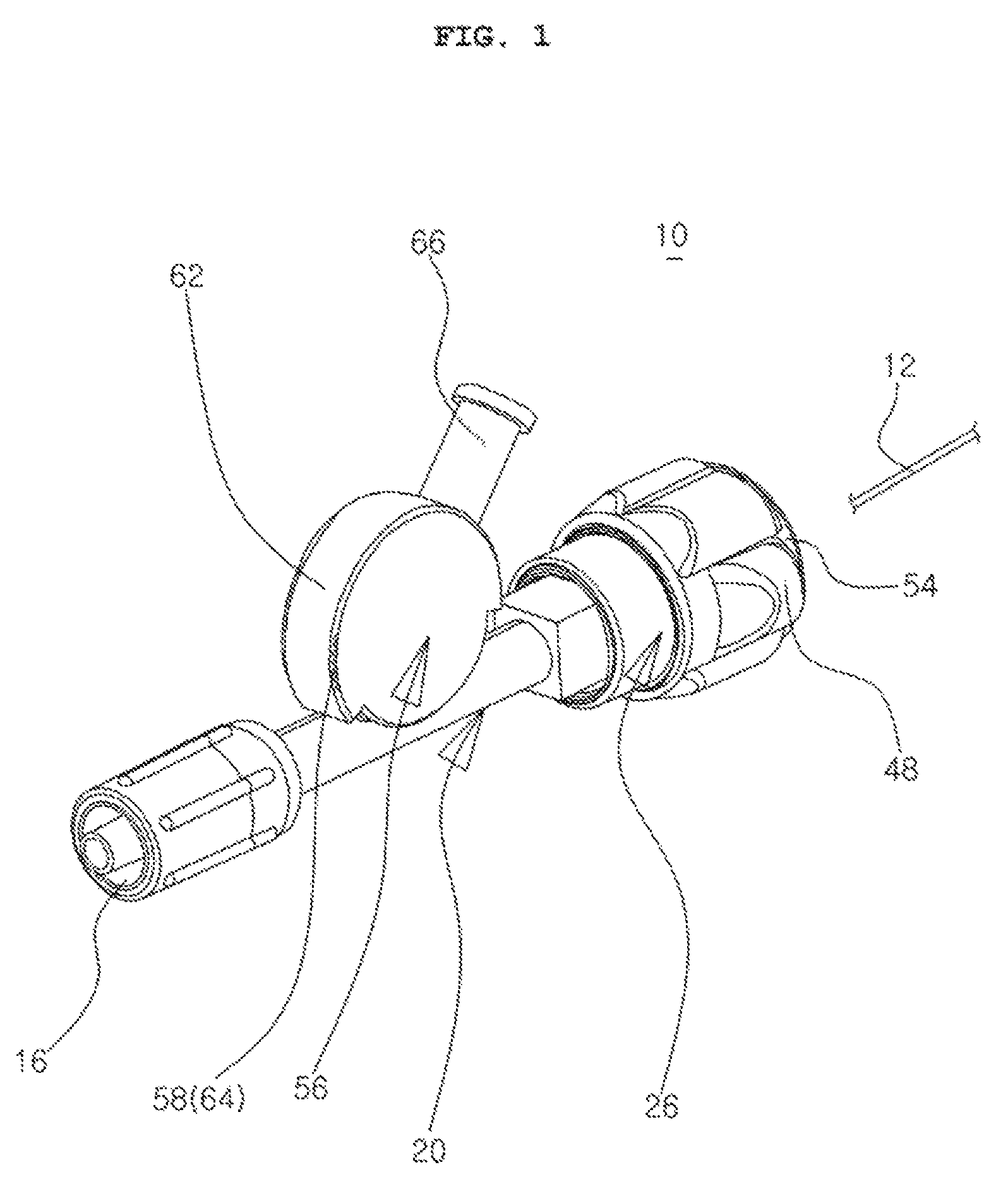
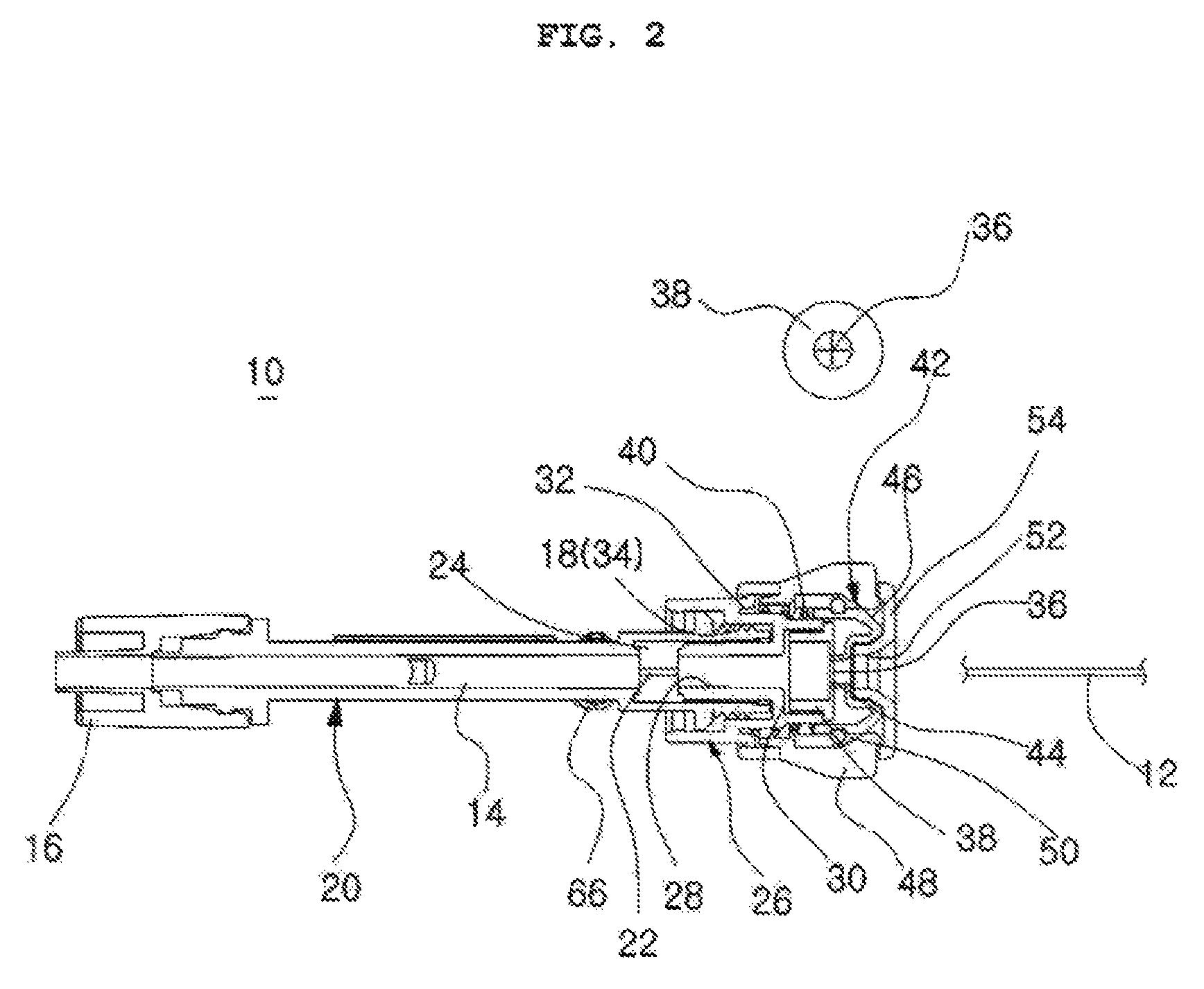
[0023]Referring to FIGS. 1 through 3, a hemostasis valve device 10 according to the present invention is provided with an insertion tube 20 which has a guide hole 14 into which different catheters 12 such as a tube, a wire, a catheter and the like are inserted along a longitudinal central axis formed in a penetrating manner, a hose connector 16 connected to a hose into which the different catheters 12 are inserted coupled to the lower portion, and a threaded portion 18 formed on the outer circumference of the upper portion.

[0024]According to the present invention, a first sealing member 24 is configured to be inserted into and seated in the upper portion of the insertion tube 20, have a through hole 22 formed along a longitudinal central axis, and have elasticity.

[0025]The insertion tube 20 additionally has a fastening tube 26 coupled to the uppe...


PUM


Abstract

The present invention relates to a hemostasis valve device which allows a wire or a catheter to be inserted into the left or right coronary artery via the femoral artery or an arm artery when a Cardiac Catheterization or Percutaneous Transluminal Coronary Angioplasty operation is performed, wherein two independent sealing members are opened and closed by press and release actions of push buttons coupled to a body and the rotation of a fastening tube, respectively, so that the leakage of blood or the inflow of outside air is simply and effectively blocked during the operation, and a drug influx tube for allowing a medicine such as a thrombolitic drug to flow into a patient during the operation pivots and is adjusted in a stepwise manner within a certain range of angles according to body conditions or movements of the patient.

Description

BACKGROUND OF THE INVENTION[0001]1. Technical Field[0002]The present invention relates to a hemostasis valve device, especially to a hemostasis valve device which allows a tube, a guide wire, or a catheter to be inserted into the left or right coronary artery via the femoral artery or an arm artery at the time of a Cardiac Catheterization or Percutaneous Transluminal Coronary Angioplasty (PTCA) operation, wherein sealing members mounted in two independent positions are opened and closed by means of press and release actions of push buttons coupled to a fastening tube as well as the rotation of the fastening tube, respectively, so that the leakage of blood or the inflow of outside air is simply and clearly shut off during the operation, and a drug influx tube for allowing a medicine such as a thrombolitic drug to flow into a patient during the surgical operation pivots and is adjusted in a stepwise manner within a certain range of angles on a basis of body conditions or movements of ...

Claims


Application Information

Patent Timeline
Patent Type & Authority Patents(United States)
IPC IPC(8): A61M39/06
CPCA61M39/0613A61B17/34A61M5/178A61M39/06A61M39/22
Inventor CHUNG, SUN
Owner HUBIOMED INC
Why Eureka
Eureka Blog
Learn More