
Seal ring

a sealing ring and inner peripheral surface technology, applied in mechanical equipment, transportation and packaging, products, etc., can solve the problems of cvt rotating parts being damaged by seizure, not being able to achieve no-load adhesion to the inner peripheral surface of the housing, and taking a long time to reach the hydraulic chamber, etc., to achieve the effect of preventing oil leakage and easy attachment to the ring groove, the time for attachment can be largely shortened

Inactive Publication Date: 2015-03-24
RIKEN CO LTD
View PDF11 Cites 1 Cited by
  • Summary
  • Abstract
  • Description
  • Claims
  • Application Information

AI Technical Summary

Benefits of technology

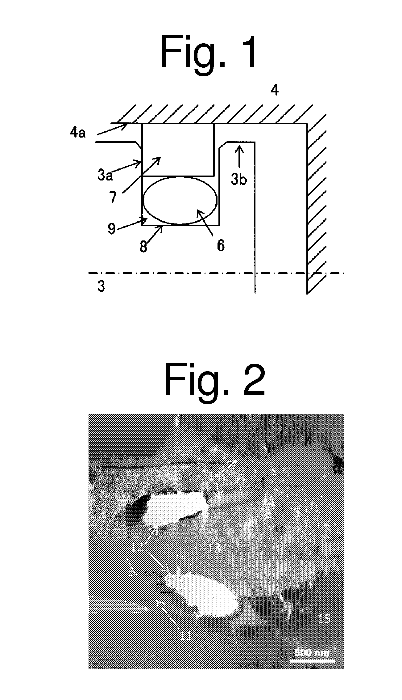
The seal ring in this invention has low compression permanent deformation when exposed to hot automatic transmission fluid, meaning it tends to return to its original state and free from compressive load. This allows the seal ring to maintain adhesion to the housing and prevent oil leakage even when no hydraulic pressure is generated. Additionally, the seal ring is made of a flexible material, easy to attach to a ring groove and used as a one-piece type, which shortens the attachment time.

Problems solved by technology

In the conventional seal ring, sufficient sealing performance is achieved in a state where a hydraulic pressure is generated, but an adhesion to the inner peripheral surface of the housing is not achieved in a no-load state.
When the engine is re-started in such a state, it takes a long time until the hydraulic chamber is filled with the oil.
When the engine is started in a state where the hydraulic chamber is not filled with the oil, a rotating part of the CVT may be damaged by seizure.
This causes a problem in which the manufacturing cost is increased and a defect of assembly of a seal ring cannot be detected.
When an engine is stopped and went into a no-load state after running, it is difficult to maintain the adhesion state (adhesion) to the inner peripheral surface of the housing.
Further, it is difficult to prevent the oil leakage from the hydraulic chamber.Patent Literature 1: Japanese Patent Application Laid-Open No. 2006-283898

Method used


Image

  • Seal ring
  • Seal ring

Examples


examples

[0034]The present invention will be described further in detail by way of the following Examples, but the present invention is not limited to these Examples.

examples 1 to 17

[0035]Materials were put in a twin screw extruder at a blending proportion shown in Table 1, and were kneaded under a condition which fell within ranges of 270 to 350° C. and 100 to 300 rpm and was properly set according to the composition, to thereby obtain a resin composition for the seal ring of the present invention. As the materials, the following commercial products were used. The resulting resin composition was injection-molded to produce various measurement samples. The surface hardness, compression permanent deformation, and amount of static leakage were measured in accordance with the following methods. The results are shown in Table 1.

A. Soft Resin

[0036]A-1. Polyester-based elastomer: Hytrel (available from DU PONT-TORAY CO., LTD.)

[0037]A-2. Polyamide-based elastomer: pebax (available from ARKEMA)

[0038]A-3. Polyester resin / acrylic rubber-based dynamic crosslinked resin: NOFALLOY TZ660-7612-BK, hardness: Shore A75 (available from NOF CORPORATION)

[0039]A-4. Polyester resin / ...

example 18

[0069]A polyester resin / acrylic rubber-based dynamic crosslinked resin as a soft resin and a vinylidene fluoride resin as a hard resin were mixed by means of a twin screw extruder equipped with a screw with a diameter φ of 92 mm in combination with a lead and a kneading disc. The polyester resin / acrylic rubber-based dynamic crosslinked resin and vinylidene fluoride resin were each supplied by a side feeder, and mixed under a shear condition of a temperature of 240° C. and a screw rotation speed of 150 rpm to obtain pellets. As the polyester resin / acrylic rubber-based dynamic crosslinked resin and vinylidene fluoride resin, the above-described commercial products were used. The mass ratio (polyester resin / acrylic rubber-based dynamic crosslinked resin: vinylidene fluoride resin) was 90:10. The obtained pellets were injection-molded in the same manner as in Example 1 to produce various measurement samples. The surface hardness, compression permanent deformation, and amount of static o...


PUM

PropertyMeasurementUnit
hydraulic pressureaaaaaaaaaa
temperatureaaaaaaaaaa
shore hardnessaaaaaaaaaa

Abstract

Provided is a seal ring manufactured from a mixture containing a soft resin including at least one of a thermoplastic elastomer and a dynamic crosslinked resin, and a hard resin including a thermoplastic resin. With this seal ring, the adhesion to the inner peripheral surface of a housing can be maintained in a no-load state where a hydraulic pressure is not generated even after use as a one-piece type for an extended period of time and oil leakage can be effectively prevented. The mixture constituting the seal ring preferably has a compression permanent deformation of 95% or lower after immersion in an automatic transmission fluid at 150° C. for 100 hours.

Description

[0001]This application is a U.S. national phase filing under 35 U.S.C. §371 of PCT Application No. PCT / JP2012 / 050637, filed Jan. 13, 2012 and claims priority under 35 U.S.C. §119 to Japanese patent application no. 2011-006156, filed Jan. 14, 2011, the entireties of both of which are incorporated by reference herein.TECHNICAL FIELD[0002]The present invention relates to a seal ring, and in particular, to a seal ring used in a continuously variable transmission (hereinafter referred to as “CVT”) which continuously changes a gear by changing the diameter of a pulley.BACKGROUND ART[0003]In a hydraulic CVT, the groove width of a pulley is correlatively changed depending on the hydraulic pressure in a hydraulic chamber, whereby the diameter of the pulley is changed to continuously change a gear. In general, a fixed pulley is integrally formed with a shaft for driving, and a movable pulley is formed in a housing that reciprocates along the shaft. A hydraulic chamber is provided in the movab...

Claims


Application Information

Patent Timeline
Patent Type & Authority Patents(United States)
IPC IPC(8): C08K3/04C08K3/30C08K7/06C08K7/14C08K7/24F16J15/3284F16J15/34
CPCF16J15/3496F16J15/3208C08K3/04C08K3/30C08K7/14C08K7/24C08K7/06Y02P20/141F16J15/20C08K3/00C08L101/00F16J15/10
Inventor ITO, HIROSHIOOWADA, AKIHIRO
Owner RIKEN CO LTD
Learn More