Contents base switching system and contents base switching method
a content and switching system technology, applied in the field of content-based switching system, can solve the problems of not being able to specify a network path, and not being able to specify a band in addition to the network path, so as to reduce the load on network resources and terminals
- Summary
- Abstract
- Description
- Claims
- Application Information
AI Technical Summary
Benefits of technology
Problems solved by technology
Method used
Image
Examples
first exemplary embodiment
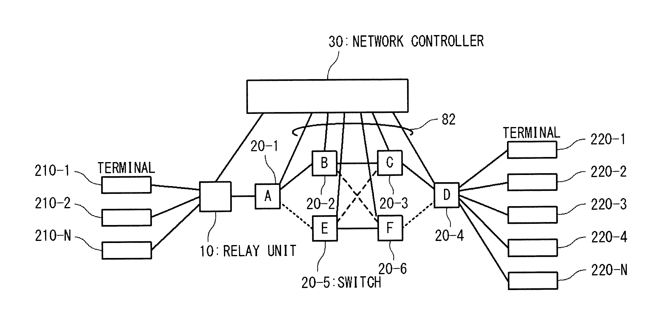
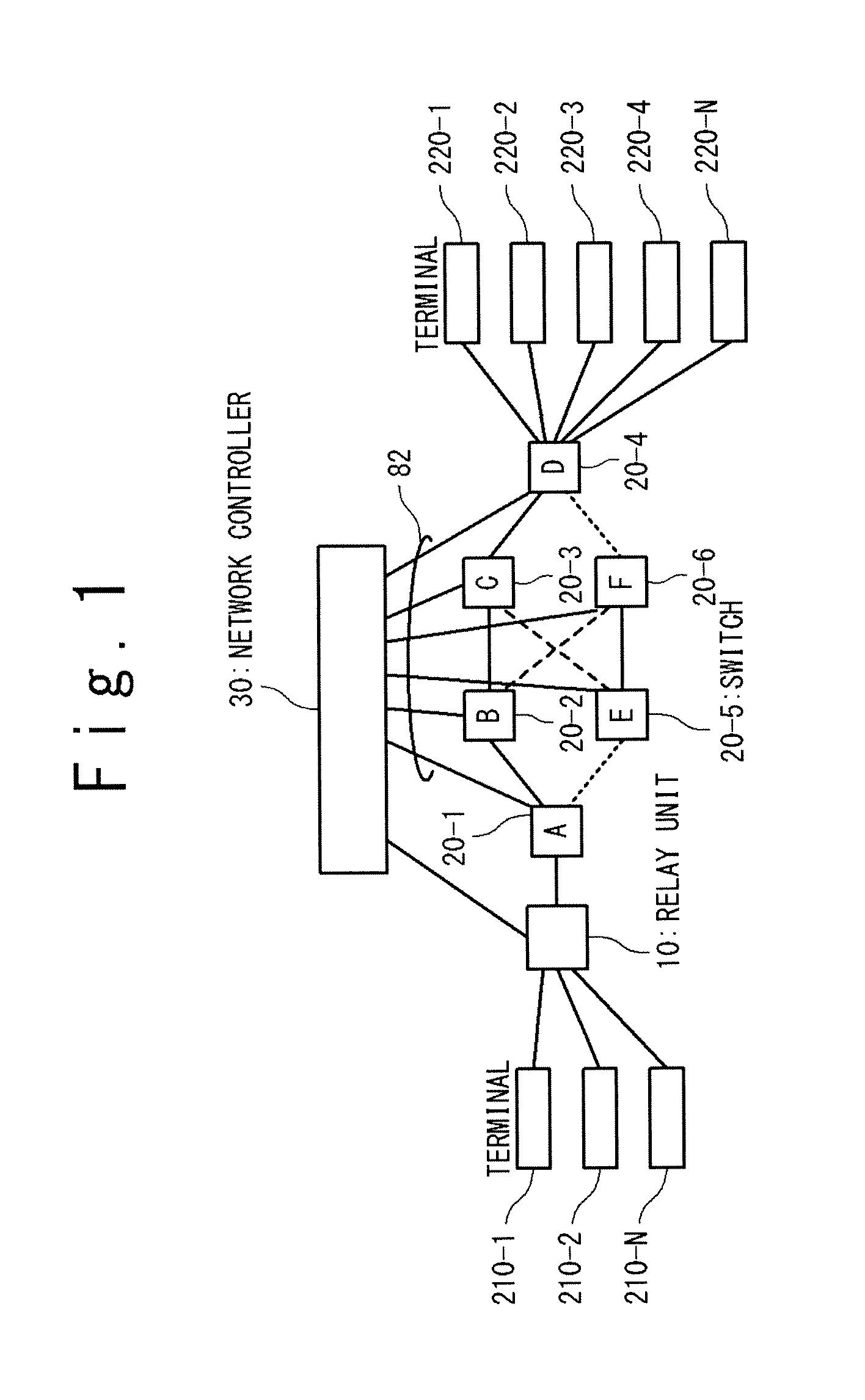
[0029]Hereinafter, a first exemplary embodiment of the present invention will be described with reference to the attached drawings. FIG. 1 shows a configuration example of a contents based switching system of the present invention. The contents based switching system of the present invention is provided with terminals 210 (terminals 210-1 to 210-N: N is a positive integer), terminals 220 (terminals 220-1 to 220-N), a relay unit 10, switches 20 (switches 20-1 to 20-6) and a network controller 30.
[0030]Here, the terminal 210 indicates a terminal contained in a group of the terminals 210-1 to 210-N. Also, the terminal 220 indicates a terminal contained in a group of the terminals 220-1 to 220-N. Also, the switch 20 indicates a switch contained in a group of the switches 20-1 to 20-6.
[0031]In the following description, each of the terminals 210-1 to 210-N is referred to as the terminal 210. Also, each of the terminals 220-1 to 220-N is referred to as the terminal 220. Also, each of the ...
second exemplary embodiment
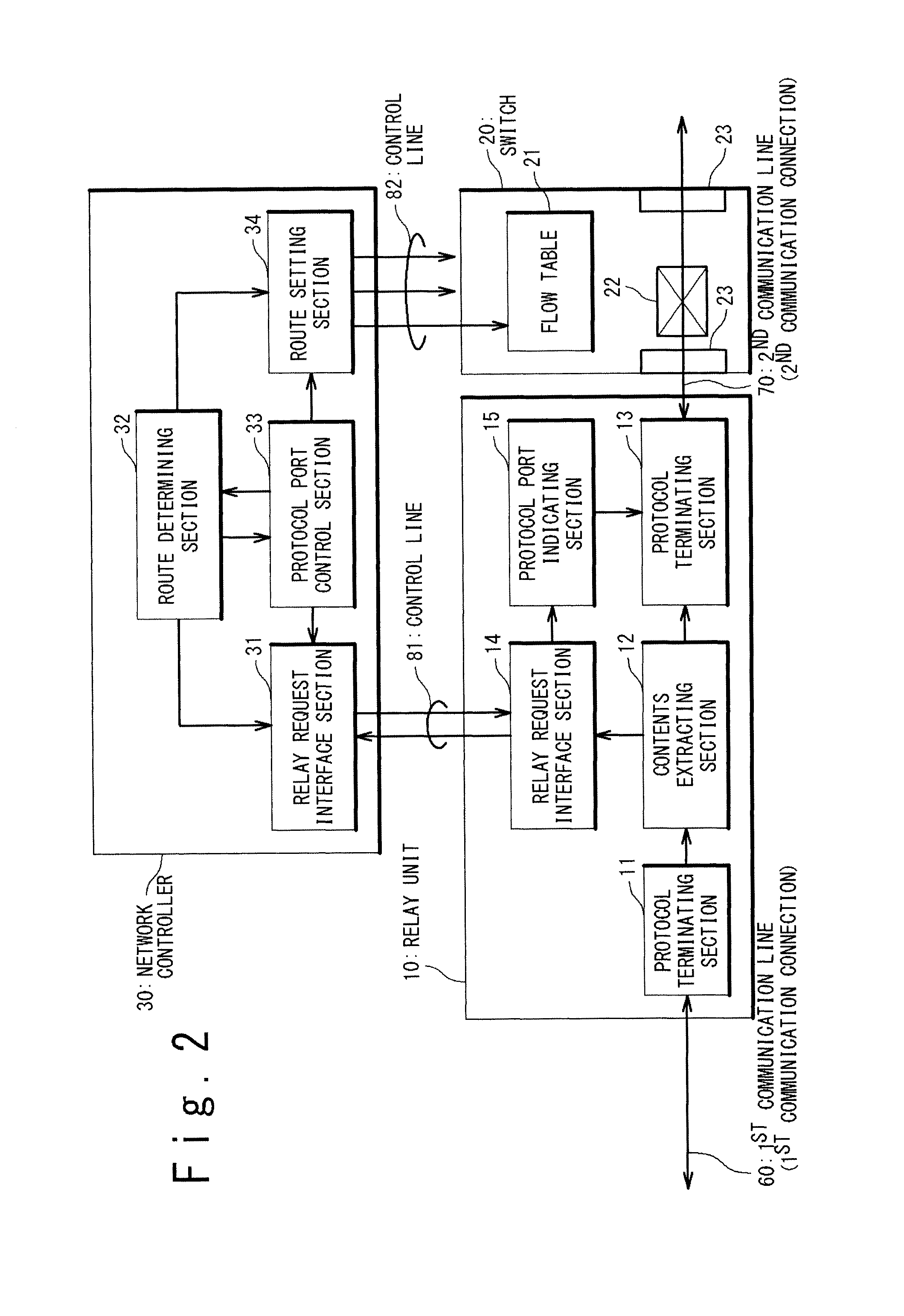
[0095]Next, the second exemplary embodiment of the present invention will be described. In the second exemplary embodiment of the present invention, a case where a flow is specified based on only the IP address without specifying the TCP port number in the flow management table of the protocol port control section 33 will be described.
[0096]The route determining section 32 of the network controller 30 determines a destination and route to the contents based on the transfer policy table. Here, the route determining section 32 assigns a destination IP address to specify the route and the destination uniquely. The route determining section 32 assigns a different destination IP address to identify a different route while a plurality of destination IP addresses are assigned to the same terminal 220.
[0097]Next, the route determining section 32 registers the flow data on the flow management table in the protocol port control section 33. Because the route determining section 32 does not man...
example 1
[0103]FIG. 7 is a sequence diagram showing a routing operation based on the contents in the relay unit 10 and the network controller 30 in case of the transfer to the terminal 220-1 from the terminal 210-1.
(1) Step S101
[0104]The terminal 210-1 transmits data to the relay unit 10. It is assumed that TCP is used for the transport. In this case, TCP connection is carried out for the IP address of the relay unit 10 or the virtual IP address representing a destination terminal group from the terminal 210-1. A TCP connection is carried out according to a sequence called “3-way handshake”. The communication of control packets (SYN, SYN-ACK, ACK) is carried out between the terminal 210-1 and the relay unit 10. When the connection establishes, the terminal 210-1 transmits the communication data containing the contents data to the relay unit 10.
(2) Step S102
[0105]The relay unit 10 transmits a relay request message which contains the contents data and the IP address data of the terminal 210-1 ...
PUM
 Abstract
Description
Claims
Application Information
 - R&D
- Intellectual Property
- Life Sciences
- Materials
- Tech Scout
- Unparalleled Data Quality
- Higher Quality Content
- 60% Fewer Hallucinations
Browse by: Latest US Patents, China's latest patents, Technical Efficacy Thesaurus, Application Domain, Technology Topic, Popular Technical Reports.
© 2025 PatSnap. All rights reserved.Legal|Privacy policy|Modern Slavery Act Transparency Statement|Sitemap|About US| Contact US: help@patsnap.com


