
Energy-harvesting system, apparatus and methods

a technology of energy harvesting and power devices, applied in the field of harvesting electromagnetic energy for power devices, can solve the problems of increasing the overall per product cost, the dc power source or power supply is not available on the market or custom made, and the practice and circuits are not as effective in providing isolation between the generator and the dc power circuit and control circuitry, so as to improve patient isolation and ensure patient safety.

Inactive Publication Date: 2015-03-03
TYCO HEALTHCARE GRP LP
View PDF20 Cites 235 Cited by
  • Summary
  • Abstract
  • Description
  • Claims
  • Application Information

AI Technical Summary

Benefits of technology

The patent application describes an electrosurgical system that uses RFID technology to generate and deliver energy to patient tissue. The system includes an energy-harvesting circuit that harvests enough energy from the energy delivery circuit to power and operate the device. This approach improves patient safety and isolation by eliminating the need for a control power connection and communication circuitry between the generator and the device. The technical effect is the improved safety and efficiency of the electrosurgical system.

Problems solved by technology

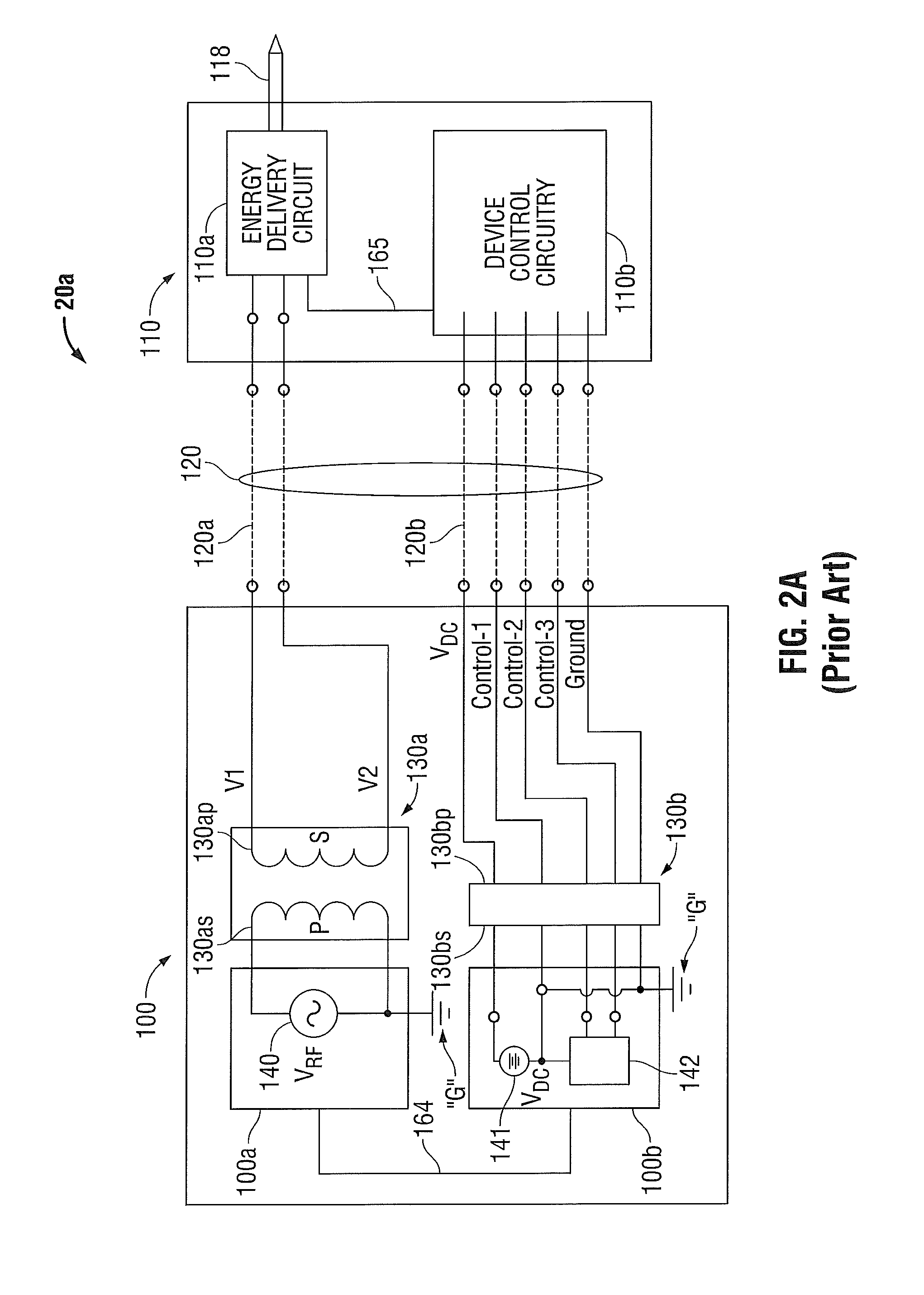
While the practice of providing an electrical isolation barrier is generally effective with respect to the energy delivery aspect of the system, these techniques, practices and circuits are not as effective in providing isolation between the generator and the DC power circuits and control circuitry in the energy delivery device.
However, providing a separate power source for the delivery device requires addition of circuitry for charge and / or charge monitoring, circuitry for preventing use when the power source is not functioning properly or not providing an adequate amount of energy for proper operation.
In addition, providing an off-the-shelf or custom DC power source or power supply to provide circuit isolation is costly thereby increasing the overall per product costs.
This, however, is not an efficient use of tag space since the energy for the “loser” antenna is not used.

Method used


Image

  • Energy-harvesting system, apparatus and methods
  • Energy-harvesting system, apparatus and methods
  • Energy-harvesting system, apparatus and methods

Examples


Embodiment Construction

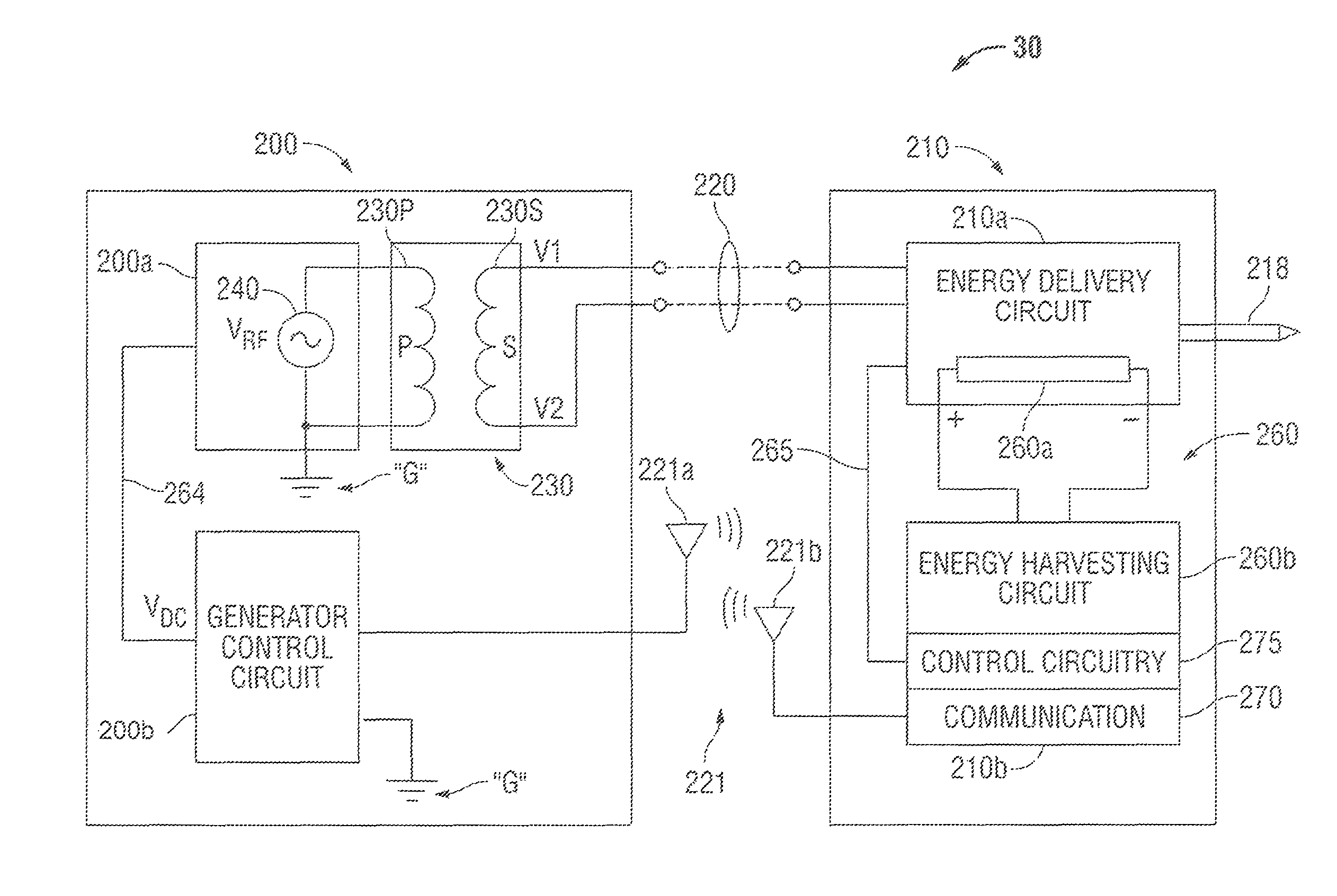
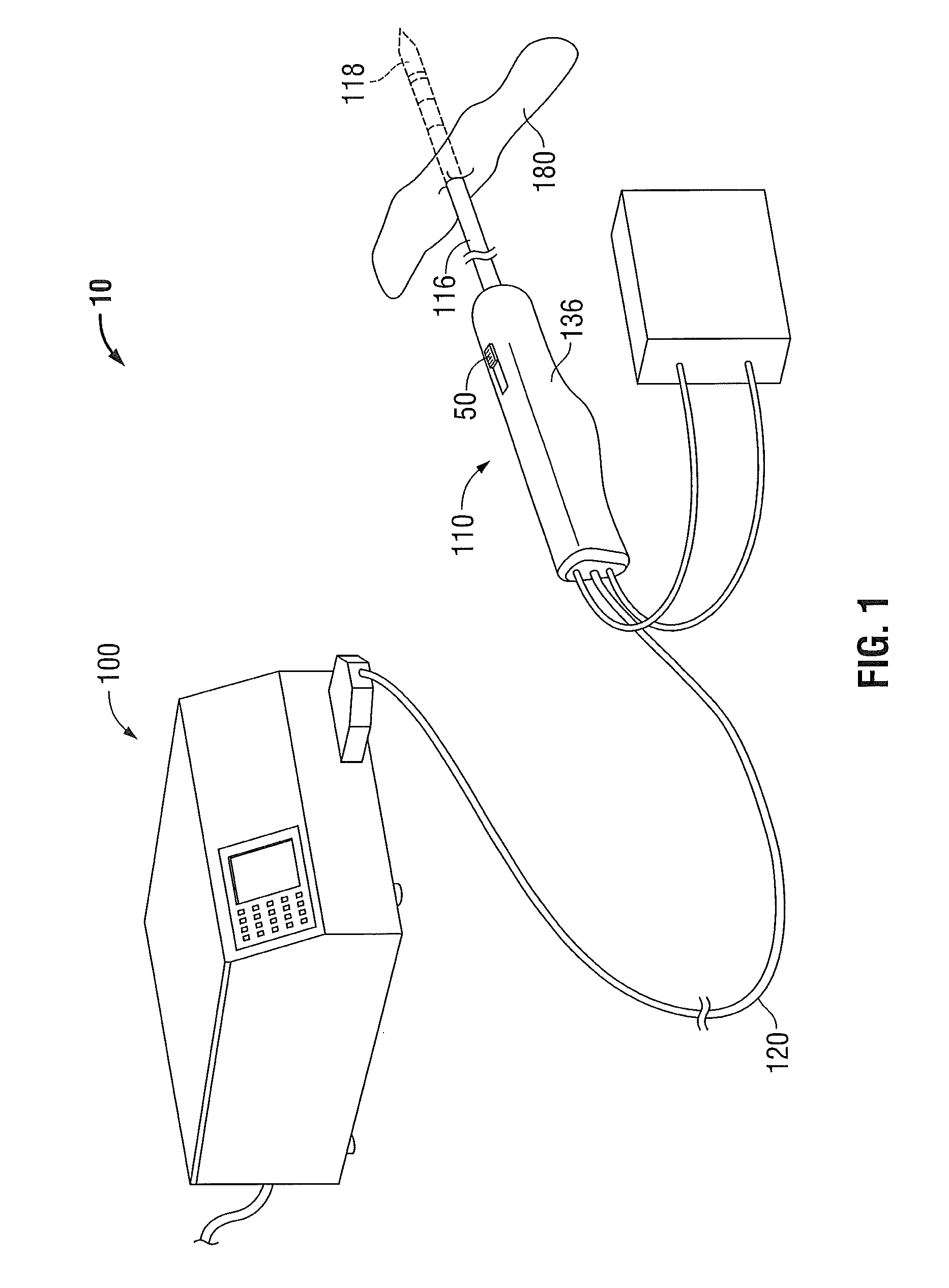
[0034]The present disclosure is related to systems, methods and apparatuses for generating energy to power electrical devices by harvesting energy from ambient electromagnetic fields. Ambient electromagnetic fields include radiation emitted from cell-phone antennas and towers, Wi-Fi transmitters, high voltage power lines, TV masts and other sources. In one example described herein, harvesting of ambient electromagnetic fields provides power to an electrosurgical device. Power may be utilized for control and / or control power thereby eliminating the need for providing control and / or control power to the electrosurgical device and improving isolation between the patient and the source of electrosurgical energy. The ambient electromagnetic field harvesting described herein may provide energy to power other electrical systems such as remote environmental sensing systems, remote sensing and control devices, wristwatches, wearable electronics, remote wireless hubs and routers and battery p...


PUM


Abstract

An electrosurgical energy delivery apparatus includes an energy delivery circuit, a control circuit and an energy-harvesting system with a plurality of energy-harvesting circuits and a voltage regulator that provides a regulated DC voltage to the energy delivery circuit and / or the control circuit. The energy delivery circuit receives an electrosurgical energy signal having a primary frequency and selectively provides the electrosurgical energy signal to an energy delivery element. The control circuit connects to the energy delivery circuit and selectively enables the flow of electrosurgical energy to the energy delivery element. The plurality of energy-harvesting circuits each include an energy-harvesting antenna tuned to a particular frequency, a matched circuit configured to receive an RF signal from the energy-harvesting antenna, rectify the RF signal and generate a DC signal, and an energy storage device that connects to the voltage regulator to receive and store the DC signal.

Description

CROSS REFERENCE TO RELATED APPLICATION[0001]The present application claims the benefit of and priority to U.S. Provisional Application Ser. No. 61 / 664,546, filed on Jun. 26, 2012, the entire contents of which are incorporated herein by reference.BACKGROUND[0002]1. Technical Field[0003]The present disclosure relates generally to harvesting electromagnetic energy for power devices, such as, for example, an electrosurgical energy delivery device used in electrosurgical energy delivery systems for delivering electrosurgical energy to tissue.[0004]2. Background of Related Art[0005]Electrosurgical energy delivery systems and procedures using electrosurgical energy are designed to safely deliver electrosurgical energy to a target tissue. The equipment, the act of energy delivery or the procedures used to deliver energy may be regulated by various governmental or industrial regulations or standards, such as, for example, FCC regulations and standards for medical equipment or electromagnetic...

Claims


Application Information

Patent Timeline
Patent Type & Authority Patents(United States)
IPC IPC(8): A61B18/04A61B17/00A61B18/00A61B18/10A61B18/12A61B18/14A61B18/18H01Q1/24H02J7/02H02J17/00
CPCA61B18/10A61B18/1206A61B18/1815H01Q1/248H02J17/00A61B18/1477A61B18/14H02J7/025A61B2018/00928A61B2018/1823A61B2017/00199A61B2017/00411A61B2018/00577A61B2018/00601A61B2018/0063A61B2018/1869A61B2018/1876H02J50/001H02J7/345H02J50/27H02J2310/23H02J50/70H02J50/20
Inventor MCPHERSON, JAMES W.
Owner TYCO HEALTHCARE GRP LP
Learn More