
Lithium ion battery and method for manufacturing of such battery

a technology of lithium ion batteries and lithium ion batteries, which is applied in the direction of non-aqueous electrolyte cells, electrode collector coatings, electrolyte layer coatings, etc., can solve the problems of high cost/lifetime ratio of lithium-ion and lithium polymer batteries, insufficient charge-discharge cycles that can be experienced, and thin-film lithium batteries that have yet to find widespread acceptance as energy storage devices

Inactive Publication Date: 2015-02-17
OERLIKON ADVANCED TECH
View PDF17 Cites 16 Cited by
  • Summary
  • Abstract
  • Description
  • Claims
  • Application Information

AI Technical Summary

Benefits of technology

The current invention is about a new method for making lithium batteries that solves issues like cycle life and safety without being too expensive. The method involves coating a substrate with a cathodic current collector and depositing layers of active electrode material, solid-electrolyte material, and an electronic conductor onto the substrate using thick film deposition techniques. The resulting battery has improved performance and safety compared to current lithium-ion and lithium polymer batteries. The method may not require depositing a thick film anode and is suitable for various applications.

Problems solved by technology

However, for many applications, the number of charge-discharge cycles that they can undergo is insufficient.
For applications where large, expensive batteries are required, for example, in all-electric or hybrid-electric vehicles and to back up solar or wind power installations, the cost / lifetime ratio for lithium-ion and lithium polymer batteries is too high.
However, to date, thin-film lithium batteries have yet to find widespread acceptance as energy storage devices.
This is primarily due to their very limited energy storage capacity per unit area and the very high cost to make them.
It is difficult to deposit thin-films greater than about 10 microns thick by PVD.
The stresses that build up in the thin-films during deposition can cause the films to delaminate or spall from the substrate.
As a result, thin-film lithium batteries must be fabricated using much less expensive thin-film deposition techniques or they will be limited to high-end niche applications with very modest capacity requirements.

Method used

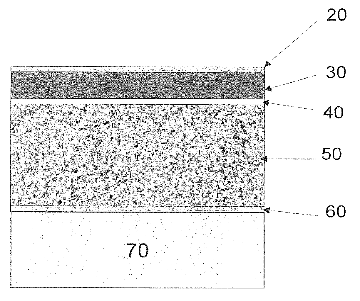
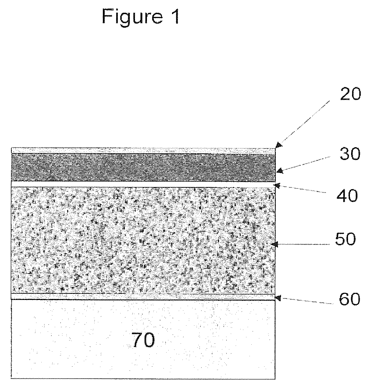
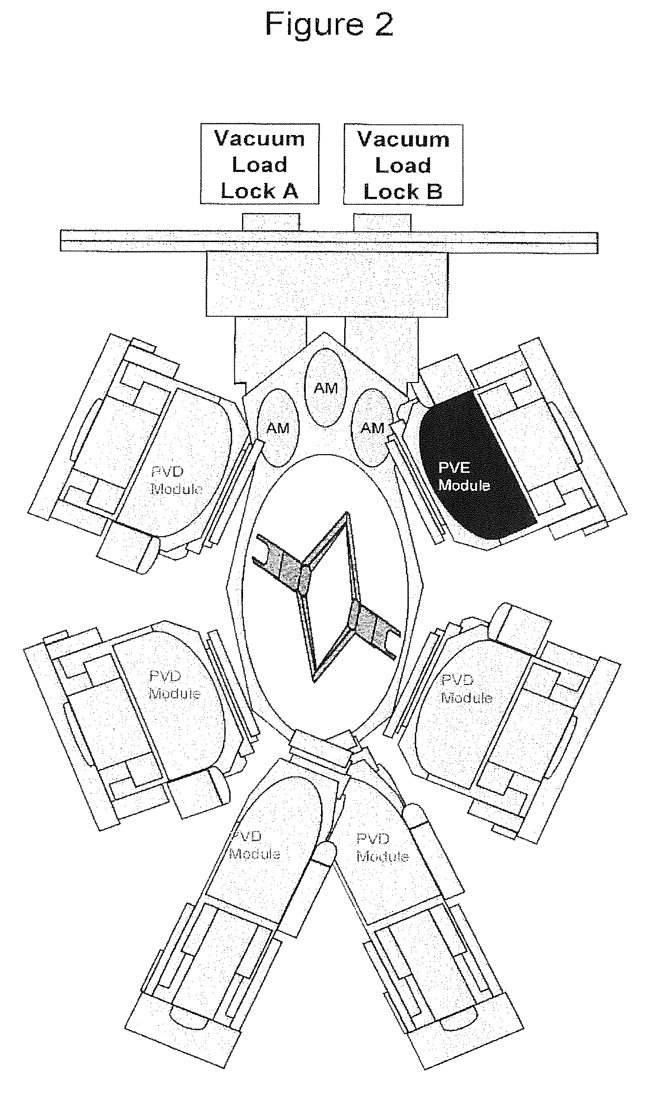

Image

  • Lithium ion battery and method for manufacturing of such battery
  • Lithium ion battery and method for manufacturing of such battery
  • Lithium ion battery and method for manufacturing of such battery

Examples


Embodiment Construction

[0025]In thin-film lithium batteries where the cathodes are typically ˜1 micron in thickness, it is possible to de-intercalate and re-intercalate reversibly ˜60% of the lithium ions contained in a thin-film LiCoO2 cathode such that little or no degradation in capacity occurs during charge-discharge cycling—thin-film lithium batteries have been reported to survive over 100,000 charge-discharge cycles under laboratory conditions. For thicker cathodes, it is difficult to access such a high fraction of the lithium content in this manner as the diffusion lengths involved become quite large for solid-state diffusion at ambient temperatures.

[0026]In lithium-ion batteries, the cathodes are fabricated to be porous: they soak up the liquid electrolyte which is then in intimate contact with the grains of the active cathode material, thus most long range lithium ion diffusion in the cathode of a lithium-ion battery occurs through the liquid phase. Nevertheless, solid-state diffusion of lithium ...


PUM

PropertyMeasurementUnit
thicknessaaaaaaaaaa
thickaaaaaaaaaa
densityaaaaaaaaaa

Abstract

The present invention provides an electrochemical cell comprising an anodic current collector in contact with an anode. A cathodic current collector is in contact with a cathode. A solid electrolyte thin-film separates the anode and the cathode.

Description

CROSS-REFERENCE TO RELATED APPLICATIONS[0001]This application is a United States national stage entry of International Application serial no. PCT / US2010 / 058275 filed Nov. 30, 2010, which claims priority to U.S. provisional patent application Ser. No. 61 / 264,974 filed Nov. 30, 2009. The contents of both of these prior applications are incorporated herein by reference in their entirety as if set forth verbatim.FIELD[0002]This invention relates to the field of electrical energy storage and is particularly related to fabricating high specific energy, high specific power rechargeable electrochemical cells for mobile electronic device, automotive and renewable energy applications.BACKGROUND[0003]Over the past several decades, the number of portable electronic devices has increased dramatically. Concomitantly, there has been a need to provide lighter, rechargeable power sources with increased electrical storage capacity. Although there have been many technological improvements in the field...

Claims


Application Information

Patent Timeline
Patent Type & Authority Patents(United States)
IPC IPC(8): H01M4/13H01M4/04H01M4/139H01M4/66H01M6/40H01M10/04H01M10/052H01M10/0525H01M10/0562H01M10/0585
CPCH01M10/052H01M4/0402H01M4/0426H01M4/13H01M4/139H01M4/661H01M6/40H01M10/0436H01M10/0562H01M10/0585Y02E60/122Y02T10/7011H01M4/0407H01M4/0404H01M10/0525H01M2300/0022H01M4/0409H01M4/0414H01M4/0419H01M4/0421Y02E60/10Y10T29/4911Y10T29/49115Y02P70/50Y02T10/70
Inventor REYNOLDS, GLYN JEREMYMAMAZZA, JR., ROBERT
Owner OERLIKON ADVANCED TECH
Learn More