Eureka AIR delivers breakthrough ideas for toughest innovation challenges, trusted by R&D personnel around the world.

Heatable injector for fuel injection in an internal combustion engine

a fuel injection and injector technology, applied in the direction of fuel injection apparatus, charge feed system, coating, etc., to achieve the effect of simple design and satisfying heating properties

Active Publication Date: 2015-02-17
DR ING H C F PORSCHE AG
View PDF28 Cites 0 Cited by
  • Summary
  • Abstract
  • Description
  • Claims
  • Application Information

AI Technical Summary

Benefits of technology

[0009]Described herein is a heatable injector of the type mentioned at the outset having particularly satisfactory heating properties, an optimum heat transfer to the fuel, and a structurally simple design.
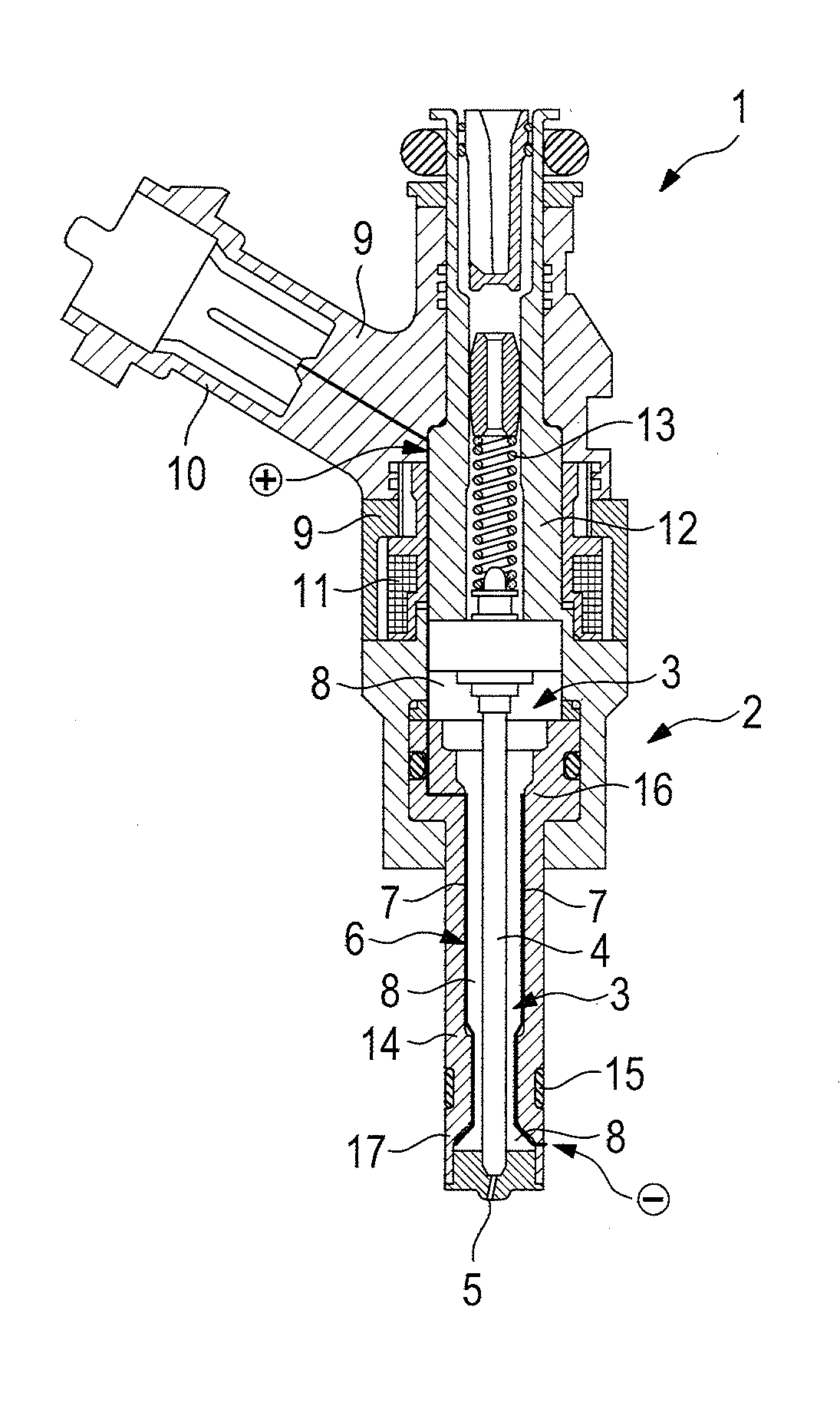
[0011]As a result of the use of a coating of this type as heating element, and therefore as a result of the use of a thin-walled, homogeneous heating element, existing injector forms, that is to say, in particular, injectors which are on the market and are not heatable, can be modified in a virtually unchanged manner for the function of heatability of the injector. Moreover, the coating forms a homogeneous contact over a large surface area with the fuel, with the result that an optimized heat transfer to the fuel is ensured.
[0013]The design according to aspects of the invention of the injector makes a sustained reduction in emissions possible. By means of the heating device which is used, the fuel is already superheated before the first injection to such an extent that it evaporates suddenly during the injection and is available in vapor form during the mixture formation and combustion. A critical advantage is the ideal mixture preparation (homogenization) and the reduction of wall deposits which contribute to the improvement of the HC and soot emissions.
[0022]The configuration of the heating element as a coating makes homogeneous heating without hot spots possible. This is possible with very low layer thicknesses of, for example, 0.1 mm. Any desired contours can be coated and heated. Temperatures of up to 500° C. are possible here. The heating device can be operated with a low voltage of 12 V / 24 V. A conductivity of up to R=1 ohm can be realized, as a result of which a high thermal output can be realized.

Problems solved by technology

This is due to the fact that the mixture regulation (lambda probe) is not yet active and the catalytic converter is too cold to effectively convert pollutants.

Method used


Image

  • Heatable injector for fuel injection in an internal combustion engine
  • Heatable injector for fuel injection in an internal combustion engine

Examples


Embodiment Construction

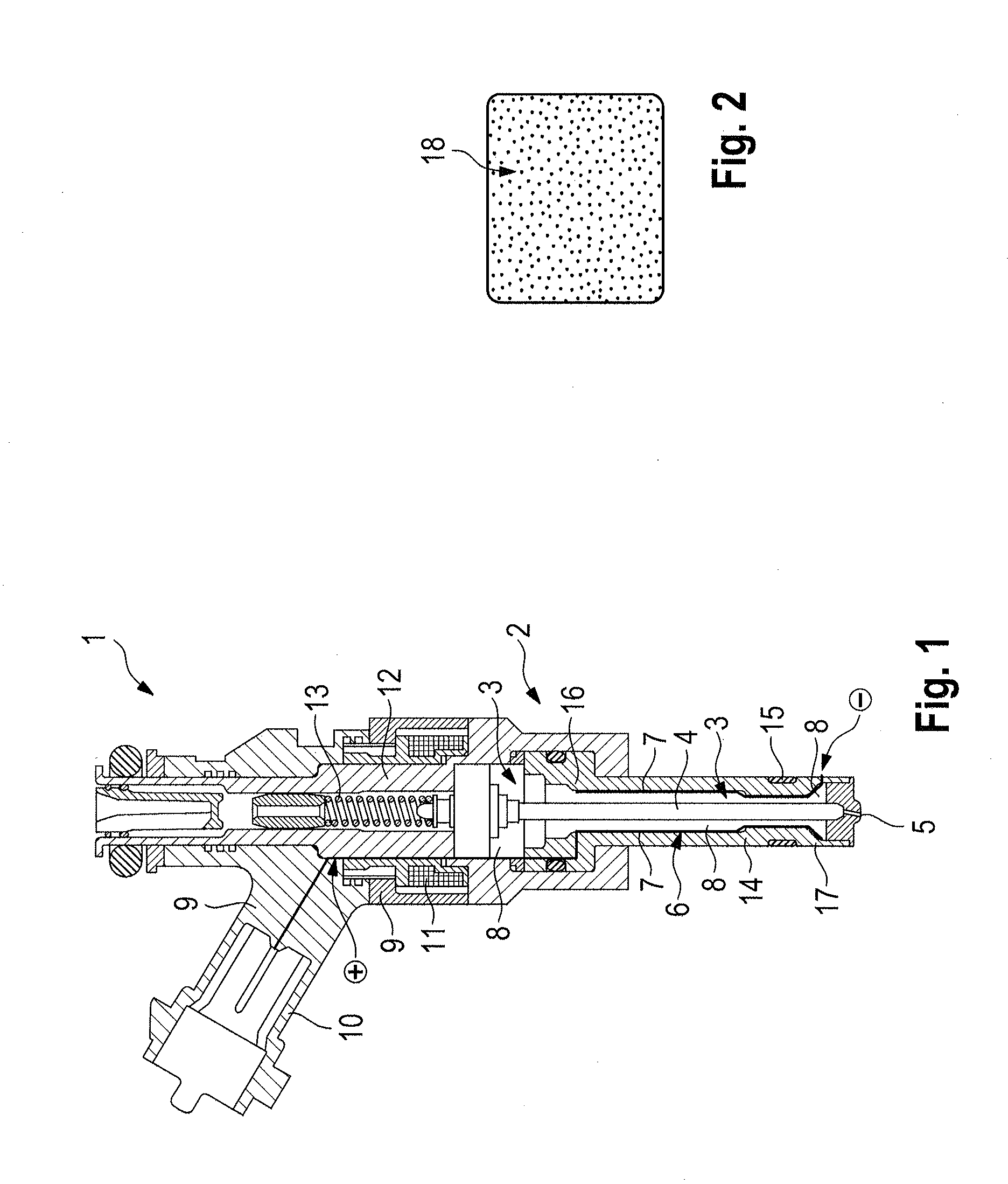
[0028]The injector 1 which is illustrated in FIG. 1 is used for fuel injection in an internal combustion engine, which is a direct injection gasoline internal combustion engine. It is provided with injectors according to aspects of the invention which are assigned to the respective cylinders of the internal combustion engine. The internal combustion engine is installed, for example, in a passenger motor vehicle.

[0029]The injector 1 has an injector housing 2, a fuel space 3 which is situated inside the injector housing 2, an adjustable injector needle 4 which is arranged in the injector housing 2 for opening and closing a fuel discharge opening 5 of the injector housing 2, and a heating device 6 which is arranged inside the injector housing 2 with a heating element 7 for heating the fuel 8 which is situated in the fuel space 3.

[0030]The injector housing 2 is configured in two pieces. A first housing part 9 receives a plug 10 for connection to a complementary electric plug part (not i...


PUM


Abstract

A heatable injector for fuel injection in an internal combustion engine, the injector having an injector housing, a fuel space which is situated inside the injector housing, an adjustable injector needle which is arranged in the injector housing for opening and closing a fuel discharge opening of the injector housing, and a heating device which is arranged inside the injector housing with a heating element for heating the fuel which is situated in the fuel space. The heating element is configured as a coating of a boundary face of the injector with respect to its fuel space, the coating being composed of a carbon nanoparticle material.

Description

CROSS-REFERENCE TO RELATED APPLICATIONS[0001]This application claims priority to German Patent Application No. DE 10 2013 102 219.7, filed Mar. 6, 2013, which is incorporated by reference herein in its entirety.FIELD OF THE INVENTION[0002]The invention relates to a heatable injector for fuel injection in an internal combustion engine, the injector having an injector housing, a fuel space which is situated inside the injector housing, an adjustable injector needle which is arranged in the injector housing for opening and closing a fuel discharge opening of the injector housing, and a heating device which is arranged inside the injector housing with a heating element for heating fuel which is situated in the fuel space.BACKGROUND OF THE INVENTION[0003]A heating element of this type on the injector serves the purpose of raising the fuel temperature, with the result that fuel can be injected into a combustion chamber of the internal combustion engine in a gaseous state. This results in ...

Claims


Application Information

Patent Timeline
Patent Type & Authority Patents(United States)
IPC IPC(8): B05B1/24F02M53/06
CPCF02M53/06F02M51/061F02M61/166F02M2200/9038
Inventor HERTWIG, MARKONAUWERCK, ANDREASSKULL, MATTEO
Owner DR ING H C F PORSCHE AG
Why Eureka
Eureka Blog
Learn More