
Vital signs monitor

a vital signs and monitor technology, applied in instruments, angiography, application, etc., can solve the problems of false or nuisance alarms, increased regulatory compliance pressure, increased costs, etc., and achieve the effect of facilitating use between patients

Active Publication Date: 2015-01-13
WELCH ALLYN INC
View PDF314 Cites 23 Cited by
  • Summary
  • Abstract
  • Description
  • Claims
  • Application Information

AI Technical Summary

Benefits of technology

The device provides seamless monitoring across various settings, reduces false alarms through improved alarm management, detects electrode failures proactively, and is user-friendly, making it suitable for diverse healthcare applications, including military use, with enhanced durability and data transmission capabilities.

Problems solved by technology

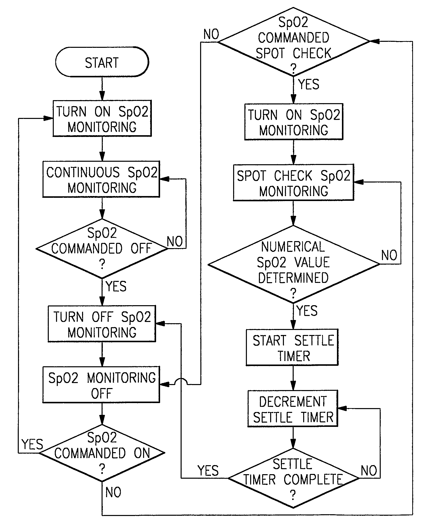
For example, the nature of monitoring devices that continuously monitor SpO2 (blood oxygen saturation) levels of a patient can cause false or nuisance alarms, particularly those patients who are of lower acuity or are ambulatory.
It is believed that present hospital healthcare dynamics, such as the general shortage of nurses, has increased pressure for regulatory compliance, rising costs, and higher acuity in patient census.
A very large challenge or barrier to this trend is that clinical staff members on medical surgical floors are generally ill-trained or adequately skilled in the use of continuous medical monitoring devices.
While this form of management / updating is often suitable for certain parameters, such as heart rate, it is not practicable for other parameters (e.g., SpO2).
Though some monitoring devices further permit manual adjustment of alarm limits, this adjustment can be a somewhat time consuming and tedious process.
As the technology for implanted pacemakers and implanted pacing electrodes has evolved, the magnitude and duration of the pulses that result at the body surface have reduced, making these pulses more difficult to detect.
Faulty incandescent light dimmers, fluorescent lights, electronic power supplies, and other assemblies generate electromagnetic interference (EMI) and other sources of electronic noise may generate such noise spikes, these spikes occurring at a rate that is twice the frequency of the power line.
If a pacer pulse detector is triggered this rapidly, it is extremely difficult for the monitoring device to calculate an accurate heart rate.

Method used


Image

  • Vital signs monitor
  • Vital signs monitor
  • Vital signs monitor

Examples


Embodiment Construction

[0081]The following description relates to a specific embodiment for a multi-parametric, vital signs monitoring device that can be used universally for a number of different patient-related applications, including ambulatory, bedside, transport, procedure, and handheld operations. It will be readily apparent, however, from the discussion that follows to those of sufficient skill that numerous variations and modifications are possible within the intended scope of the invention. In addition and throughout the text, a number of terms are used in order to provide a suitable frame of reference with regard to the accompanying drawings, including “top”, “bottom”, “front”, “rear”, “back”, and the like. These terms are not intended to be over limiting of the present invention, except in those instances where specifically indicated.

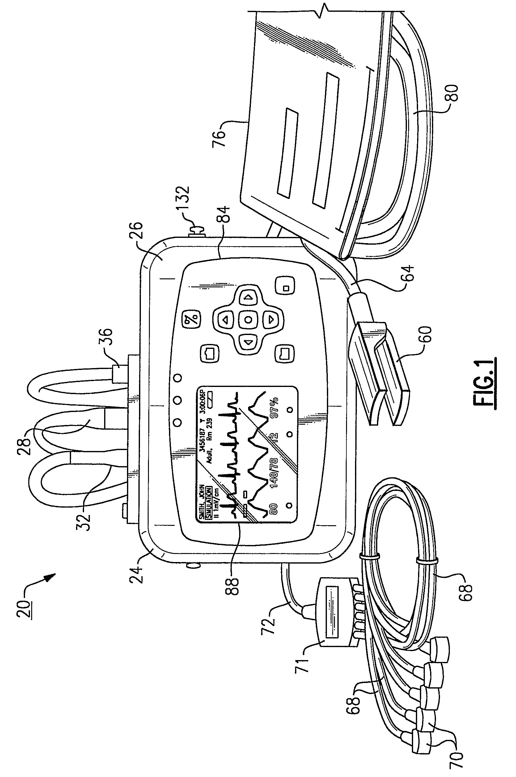
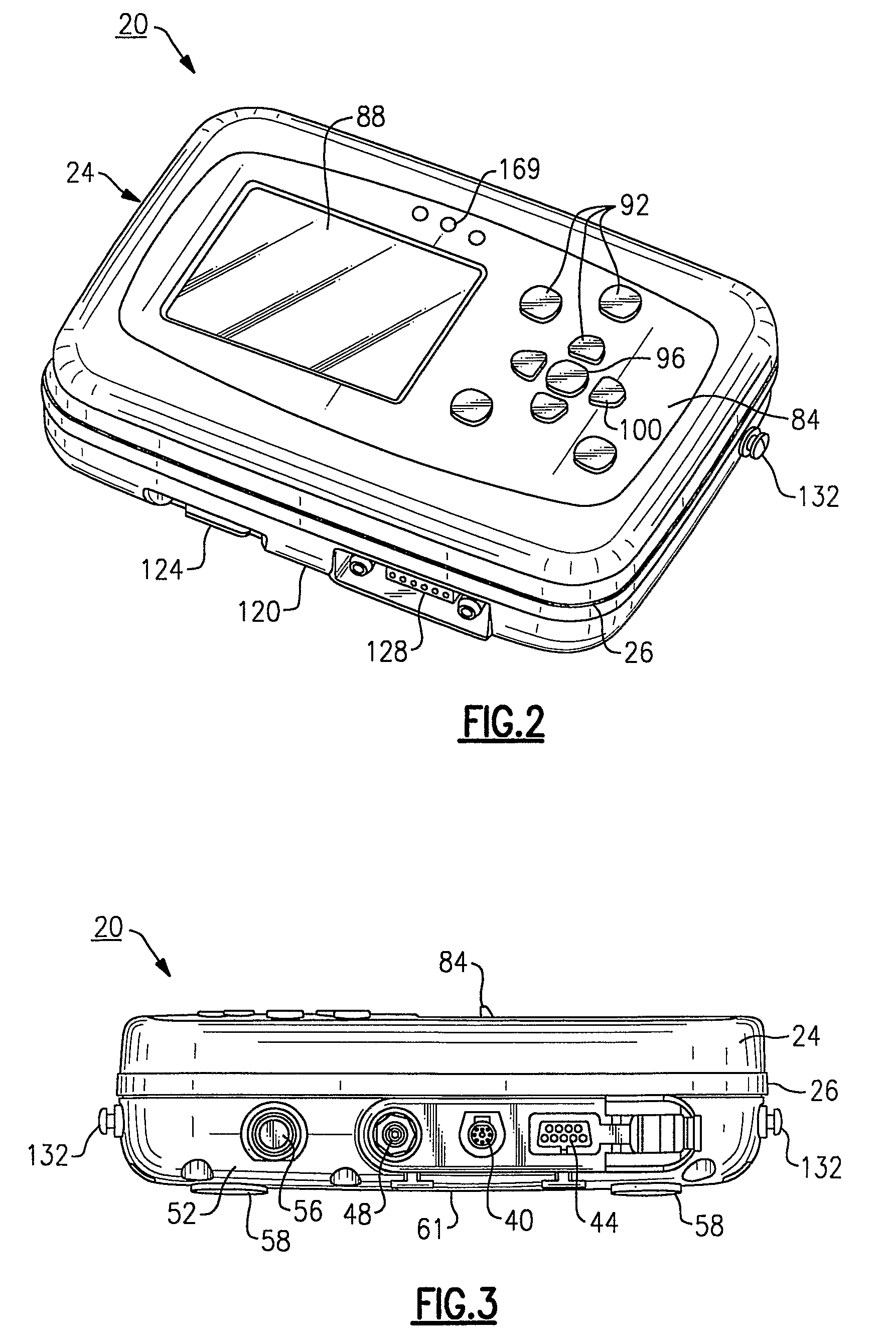
[0082]Referring to FIG. 1, the herein described patient monitoring device 20 is defined by a housing 24 that receives input from a plurality of sensors, each formi...


PUM


Abstract

A multi-parametric vital signs monitoring device configured for use as an ambulatory and a bedside monitor wherein the device can be patient-wearable and is battery powered. The monitoring device can be used with a charging cradle to provide power to the device in lieu of the battery as a power source for bedside applications, in which the cradle further serves as an intermediary device to enable a data link with a PC or other peripheral device. The monitoring device can include a wireless radio to enable bi-directional transfer of patient-related data to a separate remote station.

Description

CROSS REFERENCE TO RELATED APPLICATIONS[0001]The following patent application is a national stage application based upon PCT / US / 2006 / 001093, entitled: Vital Signs Monitor, filed Jan. 13, 2006, claiming priority of U.S. Ser. No. 60 / 643,636, filed Jan. 13, 2005, the entire contents of each above noted application being herein incorporated by reference in its entirety.FIELD OF THE INVENTION[0002]The invention relates to the field of medical diagnostic instruments and in particular to a portable, battery powered, multi-parametric, vital signs monitoring device that can be used for both ambulatory and transport applications as well as bedside monitoring. The device can be used with an optional charging cradle that supplies power and charges the contained battery. The charging cradle can additionally serve to provide an isolated data link to an interconnected portable computer allowing snapshot and trended data from the monitoring device to be printed automatically and also allowing defau...

Claims


Application Information

Patent Timeline
Patent Type & Authority Patents(United States)
IPC IPC(8): G06F19/00A61B5/00A61B5/0205A61B5/024A61B5/1455A61B5/276G16Z99/00
CPCA61B5/0205A61B5/02438A61B5/0424A61B5/14551A61B5/6843A61B5/6887A61B5/742A61B5/7475A61B5/002A61B5/0022G06F19/3406A61B5/7275A61B5/746A61B2560/0276A61B2560/0456G16H40/63G16H40/67A61B5/276G16Z99/00A61B5/33A61B5/338A61B5/021A61B5/024A61B5/0816H02J7/0042
Inventor GIBSON, GRANT S.GONDEK, CORY R.SUNDERLAND, RICHARD A.BAKER, STEVEN D.LEWIS, ROBERT T.LATHROP, BRAXTON L.DUNN, CHRISTOPHER L.KOTZER, OMER
Owner WELCH ALLYN INC
Learn More