Pressure sensor

a pressure sensor and sensor technology, applied in the field of pressure sensors, can solve the problems of reducing the sensitivity of the pressure sensor, unable to detect dynamic pressure changes with sufficient accuracy, and complex implementation of the protection of the pressure sensor against media and moistur

Inactive Publication Date: 2015-01-13
ROBERT BOSCH GMBH
View PDF23 Cites 15 Cited by
  • Summary
  • Abstract
  • Description
  • Claims
  • Application Information

AI Technical Summary

Benefits of technology

[0008]Due to the approach according to the present invention, dynamic pressure changes may be advantageously detected and evaluated with sufficient accuracy.
[0010]The pressure chamber may be completely sealed by the diaphragm, on the one hand, and by the pressure sensor element, on the other hand. The pressure sensor element may be any element which is suitable for detecting the pressure in the pressure chamber and for providing a sensor signal corresponding to the pressure. The pressure is detected via the pressure receiving surface of the pressure sensor element. The pressure receiving surface has a smaller area than the diaphragm. As a result, the small opening in the pressure chamber may have a smaller cross section or a smaller opening area than the large opening. Due to the different sizes of the openings, the shape of the pressure chamber may be adjusted in such a way that the diaphragm area is as large as possible, the area of the pressure receiving surface is as small as possible, and the volume sealed by the pressure chamber is as small as possible.
[0011]According to one embodiment, the pressure chamber may have a wall section which tapers in the direction of the small opening. In this way, the volume of the pressure chamber may be reduced, and the quality of the pressure transmission to the pressure receiving surface may be increased.
[0012]The tapering wall section may be provided with a straight design. The straight design may be implemented economically.
[0013]As an alternative, the tapering wall section may be provided with a curved design. This enables the volume of the pressure chamber to be further reduced.
[0018]Furthermore, the pressure sensor may have a cover which is designed to cover a side of the diaphragm diametrically opposed to the pressure chamber. The cover may be used to protect against mechanical damage to the diaphragm.

Problems solved by technology

Protecting the pressure sensor against media and moisture is complex in its implementation.
In particular, the sensitivity of the pressure sensor is greatly reduced, and dynamic pressure changes may not be detected with sufficient accuracy.

Method used


Image

  • Pressure sensor
  • Pressure sensor
  • Pressure sensor

Examples


Embodiment Construction

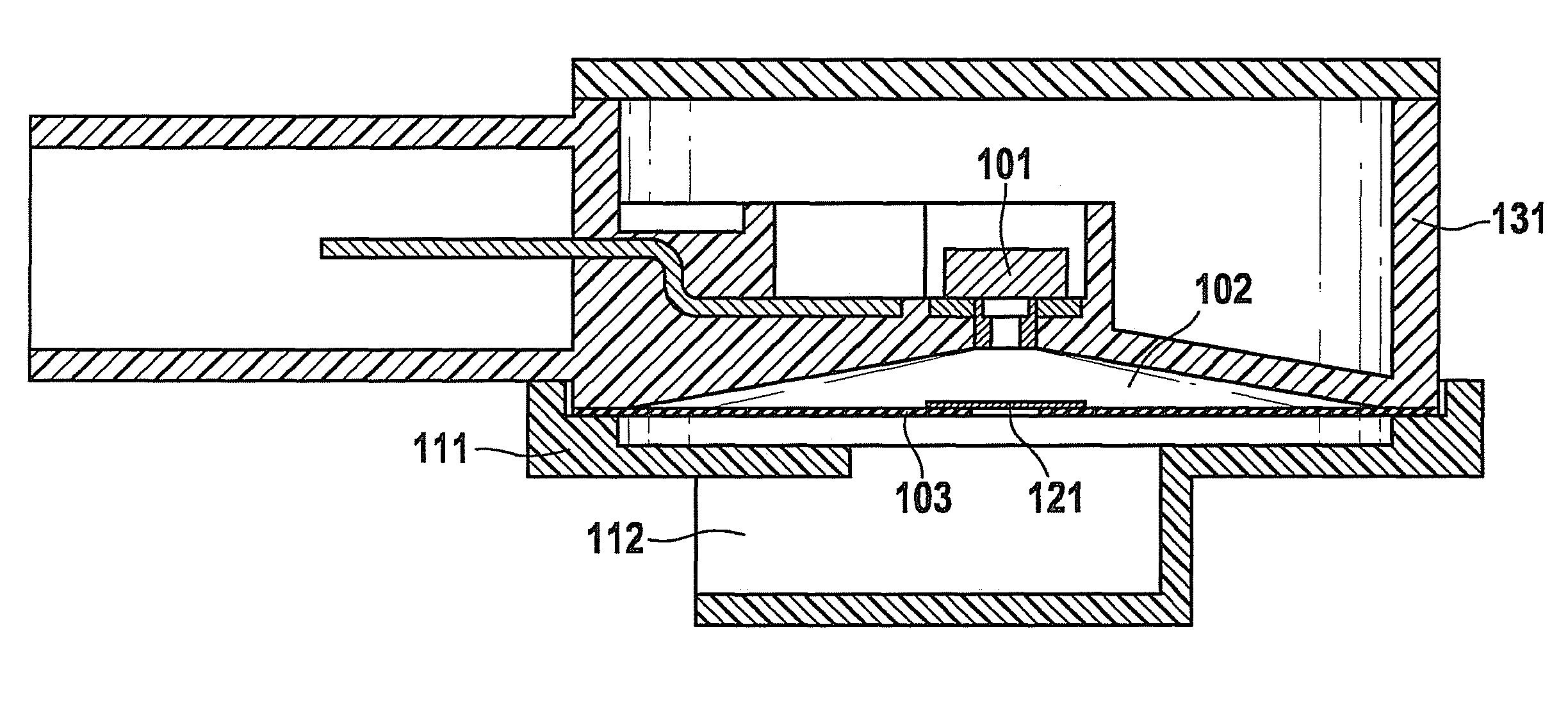
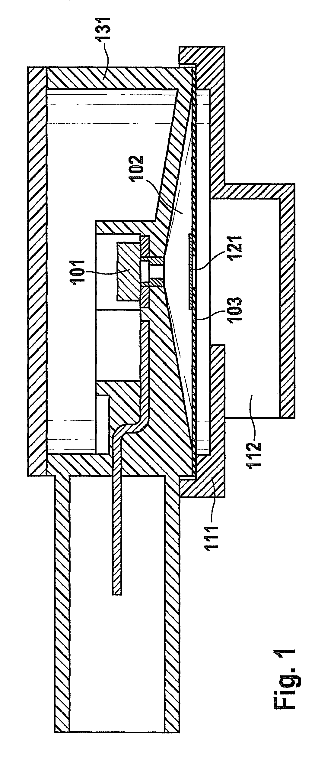
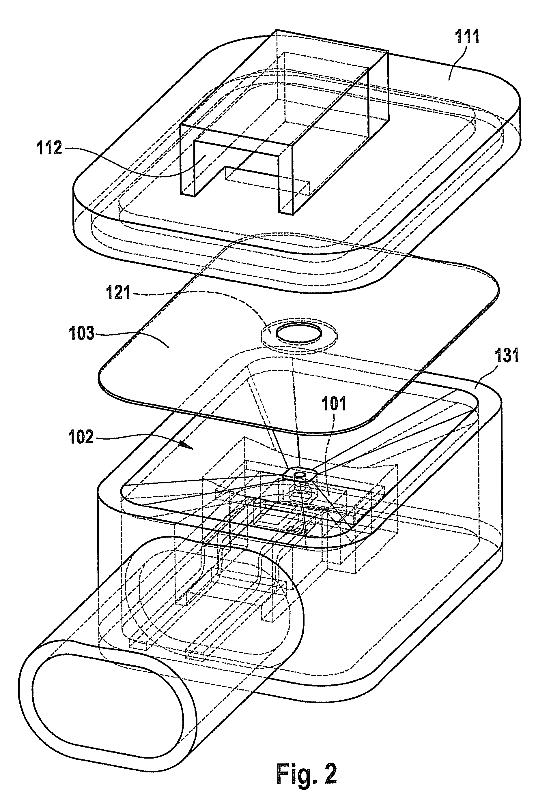
[0023]FIG. 1 shows a representation of a pressure sensor according to an exemplary embodiment of the present invention. The pressure sensor may be used, for example, as an airbag sensor of a vehicle. For this purpose, the pressure sensor may detect a pressure change induced by a collision and provide a corresponding control signal to an airbag control unit. In particular, the pressure sensor may be designed to detect rapid pressure peaks. To detect the pressure, the pressure sensor may be situated, for example, in a door of a vehicle.

[0024]The pressure sensor includes a pressure sensor element 101, a pressure chamber 102 and a diaphragm 103. Pressure chamber 102 is situated between pressure sensor element 101 and diaphragm 103. Pressure chamber 102 has a small opening and a large opening. The small opening may be situated diametrically opposed to the large opening. The small opening in pressure chamber 102 is sealed by pressure sensor element 101 and, in particular, by a pressure re...


PUM

PropertyMeasurementUnit
pressureaaaaaaaaaa
dynamic pressureaaaaaaaaaa
areaaaaaaaaaaa

Abstract

A pressure sensor is provided which is suitable as an airbag sensor of a vehicle. The pressure sensor includes a pressure chamber having a small opening and a large opening, a pressure sensor element having a pressure receiving surface, and a diaphragm. The diaphragm is designed to seal the large opening. The pressure sensor element is designed to seal the small opening at least using the pressure receiving surface.

Description

CROSS-REFERENCE TO RELATED APPLICATIONS[0001]This application is a National Stage application of international application PCT / EP09 / 62048 filed on Sep. 17, 2009, which claimed priority to German patent application No. 102008043644.5 filed on Nov. 11, 2008. Both the international application and the German application are incorporated herein by reference in their entireties.FIELD OF THE INVENTION[0002]The present invention relates to a pressure sensor, which is suitable as an airbag sensor of a vehicle.SUMMARY OF THE INVENTION[0003]German Patent No. DE 10 2006 024 666 describes an impact detection device in which at least one air pressure sensor situated in a side part of a vehicle detects the impact as a function of a signal.[0004]In a side airbag sensor based on a pressure sensor (PPS: peripheral pressure sensor), the airbag is triggered in the event of a crash due to the change in pressure in a closed volume, for example of a vehicle door. Protecting the pressure sensor against me...

Claims


Application Information

Patent Timeline
Patent Type & Authority Patents(United States)
IPC IPC(8): G01L7/08B60R21/00B60R21/0136
CPCB60R21/0136B60R2021/0006
Inventor KUNERT, PETER
Owner ROBERT BOSCH GMBH
Why Eureka
Try Eureka