Bidirectional level shifter

Inactive Publication Date: 2014-12-23
RICHTEK TECH
View PDF2 Cites 3 Cited by
  • Summary
  • Abstract
  • Description
  • Claims
  • Application Information

AI Technical Summary

Problems solved by technology

The above prior art has the drawback that a regulator circuit is required to provide the voltage Vp in the bidirectional level shifter 10, but the regulator circuit occupies a large area in an IC chip and consumes current, and the NMOS switch in the regulator circuit requires a large area to reduce its body effect.

Method used


Image

  • Bidirectional level shifter
  • Bidirectional level shifter
  • Bidirectional level shifter

Examples


Embodiment Construction

[0017]The drawings as referred to throughout the description of the present invention are for illustrative purpose only, but not drawn according to actual scale. The orientation wordings in the description such as: above, under, left, or right are for reference with respect to the drawings, but not for limiting the actual product made according to the present invention.

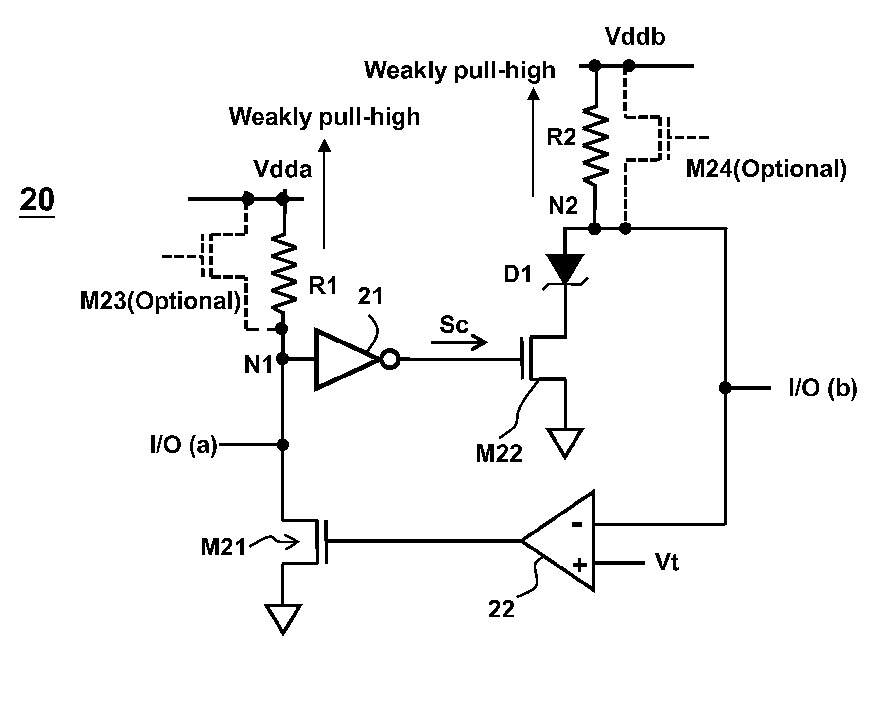
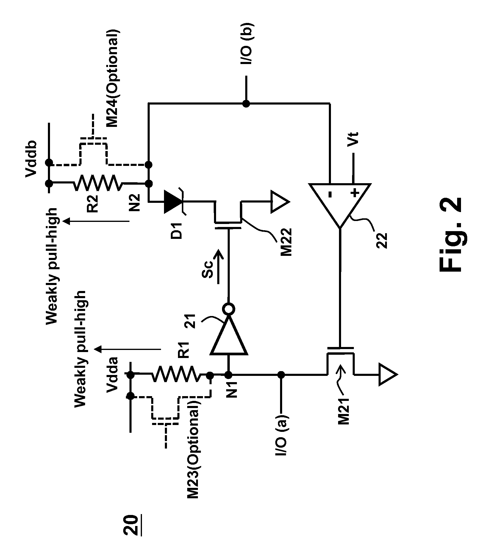
[0018]FIG. 2 shows an embodiment of the bidirectional level shifter 20 according to a perspective of the present invention, which can be used for bidirectional serial data transmission. The bidirectional level shifter 20 includes: a first signal terminal I / O(a); a second signal terminal I / O(b); a first switch M21, coupled between the first signal terminal I / O (a) and a ground level, to control a conduction status between the first signal terminal I / O(a) and the ground level; an inverter 21, receiving a signal from the first signal terminal I / O(a) through a first common node N1, and transmitting a control signal Sc acc...


PUM


Abstract

The invention provides a bidirectional level shifter which includes: a first signal terminal; a second signal terminal; a first switch, coupled between the first signal terminal and ground; an inverter receiving a signal from the first signal terminal; a Schottky diode including an anode and a cathode, the anode receiving a signal from the second signal terminal; a second switch, coupled between the cathode of the Schottky diode and the ground; a comparing circuit, comparing a reference voltage and a voltage at the second signal terminal to control the first switch, wherein the reference voltage is lower than a forward bias voltage of the Schottky diode; a first voltage source coupled to the first common node; and a second voltage source coupled to the second common node.

Description

BACKGROUND OF THE INVENTION[0001]1. Field of Invention[0002]The present invention relates to a bidirectional level shifter, especially a bidirectional level shifter using a Schottky diode to provide a voltage difference.[0003]2. Description of Related Art[0004]A bidirectional level shifter is a commonly used signal input / output device, for example, used for bidirectional serial data transmission. FIG. 1 shows a bidirectional level shifter 10 disclosed by U.S. Pat. No. 7,822,890, wherein one of the signal terminal I / O (a) and the signal terminal I / O(b) can be a signal input terminal, and the other can be a signal output terminal. The bidirectional level shifter 10 includes two switches M1 and M2, an inverter 11, and a comparator 12. The voltage Vt is a low reference voltage between a logic high voltage level and a logic low voltage level of the input signal to the signal terminal I / O (b) when the signal terminal I / O(b) acts as the input terminal, and the voltage Vp is a low voltage s...

Claims


Application Information

Patent Timeline
Patent Type & Authority Patents(United States)
IPC IPC(8): G11C7/10H03K19/003G11C11/4093H03K19/185H03K19/0185H03K19/0175
CPCH03K19/01759H03K19/00361H03K19/0185
Inventor WEI, CHINYUANJIANG, SHIUESHR
Owner RICHTEK TECH
Why Eureka
Try Eureka