External cavity tunable laser

a laser and external cavity technology, applied in the field of photonics, can solve the problems of higher cost, higher manufacturing difficulty, and larger siz

Inactive Publication Date: 2014-12-09
GP PHOTONICS INC
View PDF9 Cites 0 Cited by
  • Summary
  • Abstract
  • Description
  • Claims
  • Application Information

AI Technical Summary

Benefits of technology

[0033]The invention has the advantages and positive effects that:
[0034]In this invention, an active polarization rotator, a polarization beam splitter, two etalons and two total reflection mirrors are used to form two laser resonant sub-cavities to achieve high spectrum density, narrow-frequency bandwidth within a wide spectrum range. The requirement on the filtering bandwidth of the optical filter is reduced by half for the same output properties with a single cavity laser. Stable laser output with 25 GHz frequency interval is realized by an optical filter with 50 GHz frequency interval, and the etalons having a 50 GHz transmission spectrum peak interval. Both the requirement on the filtering bandwidth of the tunable optical filter and the requirement on the transmission spectrum peak frequency interval of the etalons are reduced. And furthermore, the difficulty in manufacturing the tunable optical filter and the etalons is dramatically reduced. The external cavity tunable laser in this invention is compact with high performance and low cost for volume production and easy installation, achieves high spectral density, narrow spectral bandwidth and tunable stable laser output within a wide spectrum range, and significantly reduces the difficulty in manufacturing the tunable optical filter and the etalons.

Problems solved by technology

An optical filter such as a conventional optical grating filter or an acousto-optic filter with narrow bandwidth means higher manufacturing difficulty and higher cost, similarly, an etalon with narrow transmission spectrum interval means larger size, high manufacturing difficulty and cost.

Method used


Image

  • External cavity tunable laser
  • External cavity tunable laser
  • External cavity tunable laser

Examples


Embodiment Construction

[0016]It is an objective of the invention to overcome the shortcomings in the prior art and to provide a tunable laser with low cost, small size, easy manufacturing and high performance.

[0017]The technical scheme below is adopted by the invention for solving the technical problems in the prior art.

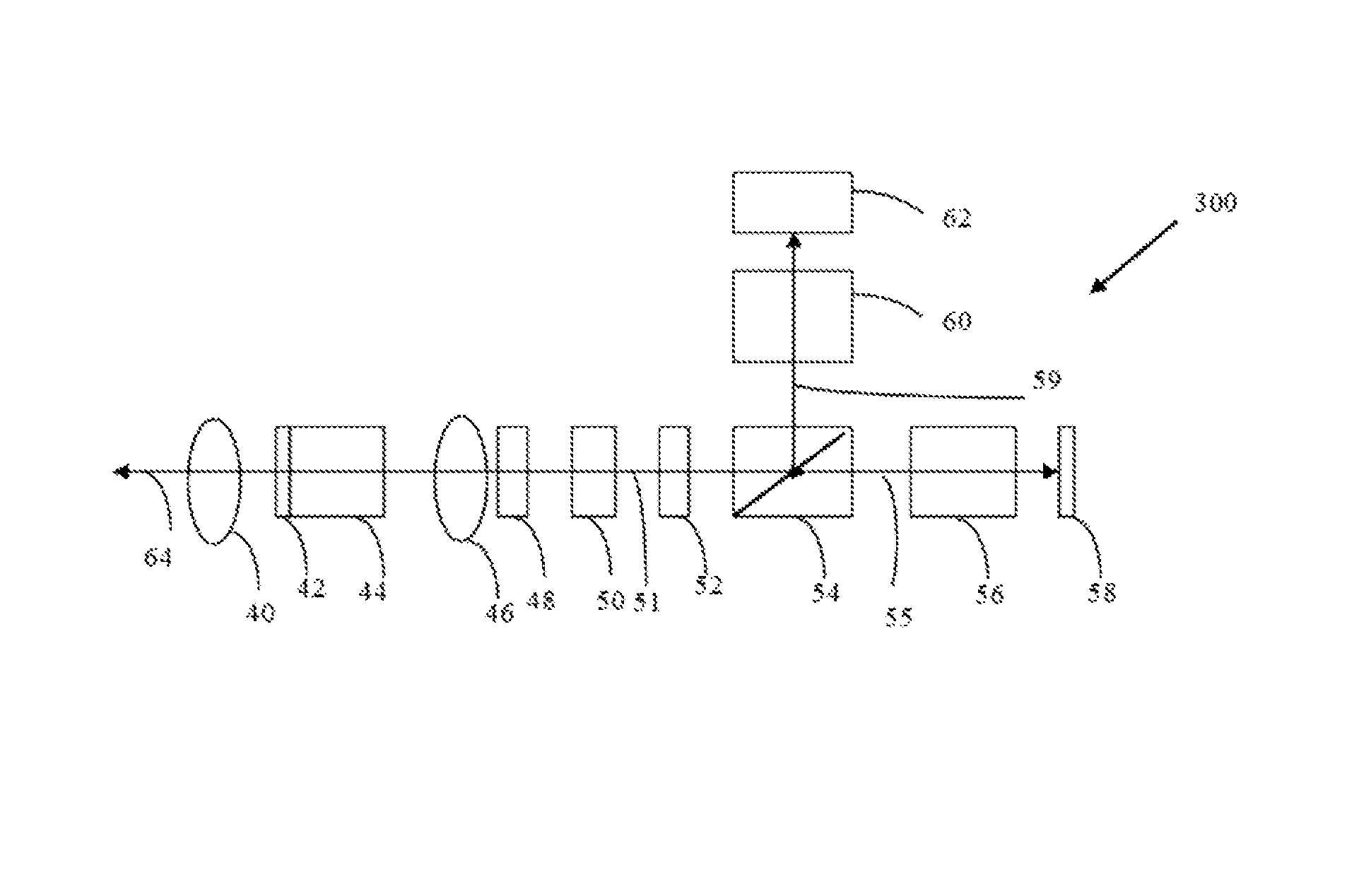
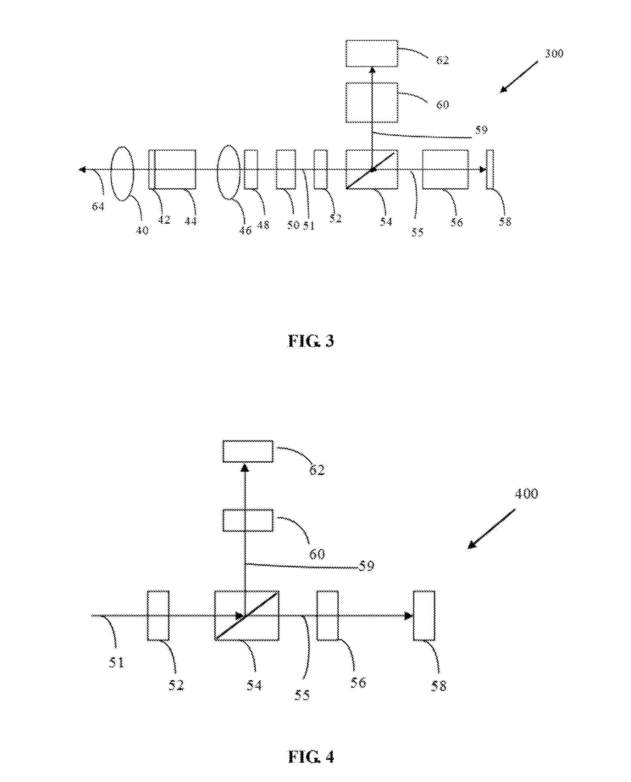
[0018]An external cavity tunable laser, comprising an extracavity collimating lens arranged outside the laser cavity, and a laser output mirror, a laser gain medium, an intracavity collimating lens, an active optical phase modulator and a tunable optical filter all arranged sequentially inside the laser cavity, the laser further comprises:

[0019]an active polarization rotator arranged behind the tunable optical filter for rotating the polarization direction of incident linearly polarized light by 90 degrees,

[0020]a polarization beam splitter arranged behind the active polarization rotator with total transmission for incident parallel polarized light and reflecting incident vertically polari...


PUM


Abstract

The invention relates to an external cavity tunable laser. The laser comprises an extracavity collimating lens arranged outside a laser cavity, and a laser output mirror, a laser gain medium, an intracavity collimating lens, an active optical phase modulator and a tunable optical filter all arranged sequentially inside the laser cavity. The laser further comprises an active polarization rotator arranged behind the tunable optical filter, a polarization beam splitter arranged behind the active polarization rotator, a first etalon and a first total reflection mirror arranged in the direction vertical to the optic axis of a laser cavity output lens, a second etalon and a second total reflection mirror arranged in the direction of the optic axis of the laser cavity output lens, and a laser drive and control circuit. The invention is compact with high performance and low cost for volume production and easy installation, achieves high spectral density, narrow spectral bandwidth and tunable stable laser output within a wide spectrum range, and significantly reduces the difficulty in manufacturing the tunable optical filter and the etalons.

Description

CROSS-REFERENCE TO RELATED APPLICATION[0001]The application is a continuation of PCT / CN2011 / 075697 (filed on Jun. 13, 2011), which claims priority of Chinese patent application 201110146997.8 (filed on Jun. 2, 2011), the contents of which are incorporated herein by reference, as if fully set forth herein.FIELD OF THE INVENTION[0002]The invention belongs to the field of photonics, and in particular relates to an external cavity tunable laser.BACKGROUND OF THE INVENTION[0003]Currently, most of the modern communication systems are based on fiber communication network, and fiber network has offered unprecedented huge capacity and installation flexibility and is able to support a variety of broadband applications that are under ceaseless development. Broadband and multi-channel tunable laser could help utilize the present fiber network redevices more efficiently. Data flow can be transferred from a congested channel to an unused channel by means of dynamic provision of broadband, thus In...

Claims


Application Information

Patent Timeline
Patent Type & Authority Patents(United States)
IPC IPC(8): H01S5/028H01S5/14H01S3/107H01S3/00H01S3/10H01S3/106
CPCH01S3/0085H01S5/141H01S3/107H01S3/1068H01S5/142H01S5/0287
Inventor GAO, PEILIANG
Owner GP PHOTONICS INC
Why Eureka
Try Eureka