
Expandable intervertebral implant and associated surgical method

a technology of intervertebral implants and surgical methods, which is applied in the field of minimally invasive, surgically implantable spinal devices and systems, and can solve the problems of increased stress on other vertebral elements, increased morbidity associated with these more invasive procedures, and increased blood loss

Active Publication Date: 2014-11-25
INNOVA SPINAL TECH
View PDF22 Cites 134 Cited by
  • Summary
  • Abstract
  • Description
  • Claims
  • Application Information

AI Technical Summary

Benefits of technology

The present invention is an expandable intervertebral implant that can be used in the treatment of spine injuries, diseases, or degeneration. The implant is placed between two vertebral bodies and can be deployed to distract, realign, or stabilize them. The implant has superior and inferior members that are designed to engage the concave surfaces of the associated bony intervertebral endplates. The implant can be secured in place using ridges or friction structures on its external surface. The technical effect of the invention is the ability to provide a minimally invasive and effective treatment for spine disorders.

Problems solved by technology

Typically, these devices require sizable working channels, soft tissue disruption, nerve root retraction, and significant bone resection, thereby increasing the resulting stress on other vertebral elements.
Further, morbidities associated with these more-invasive procedures include, but are not limited to, greater blood loss, longer recovery, and increased risk of surgical site infection.
However, no such alternative devices or systems are currently available, at least not any that are adequate.

Method used


Image

  • Expandable intervertebral implant and associated surgical method
  • Expandable intervertebral implant and associated surgical method
  • Expandable intervertebral implant and associated surgical method

Examples


Embodiment Construction

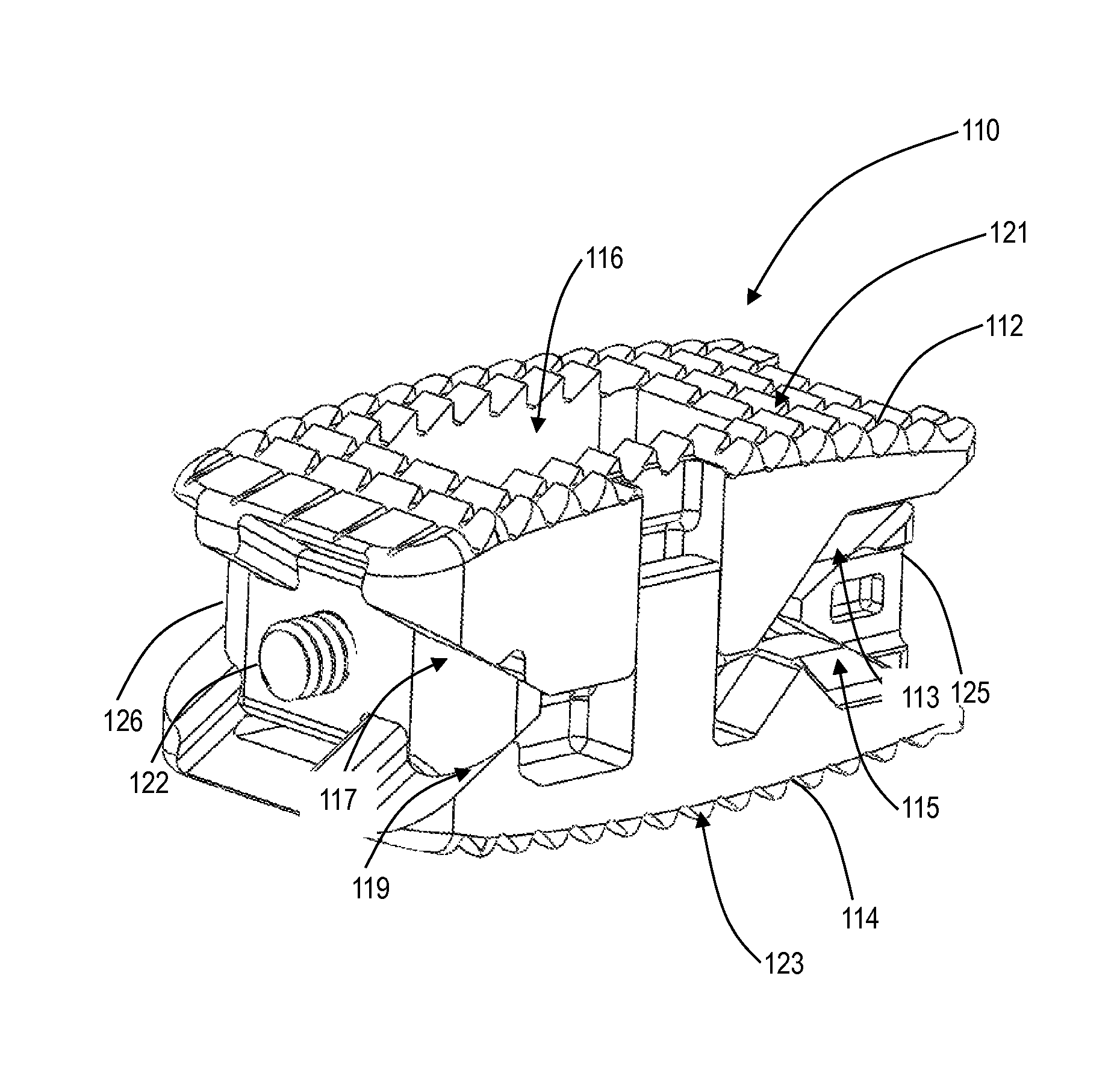
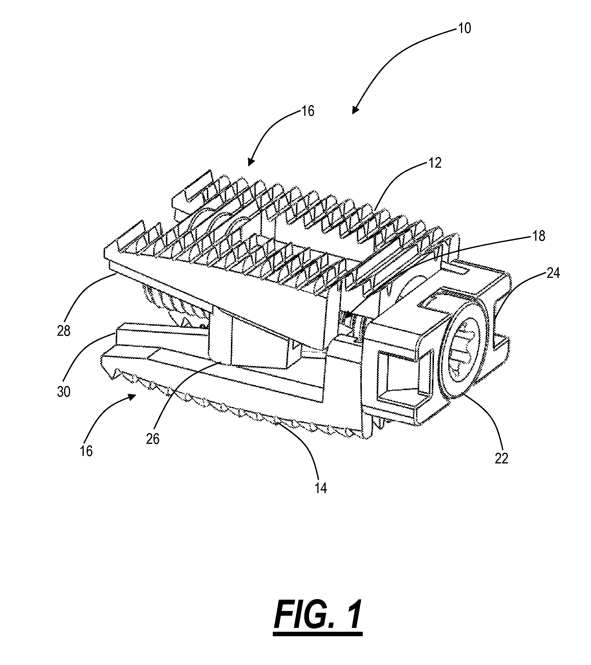
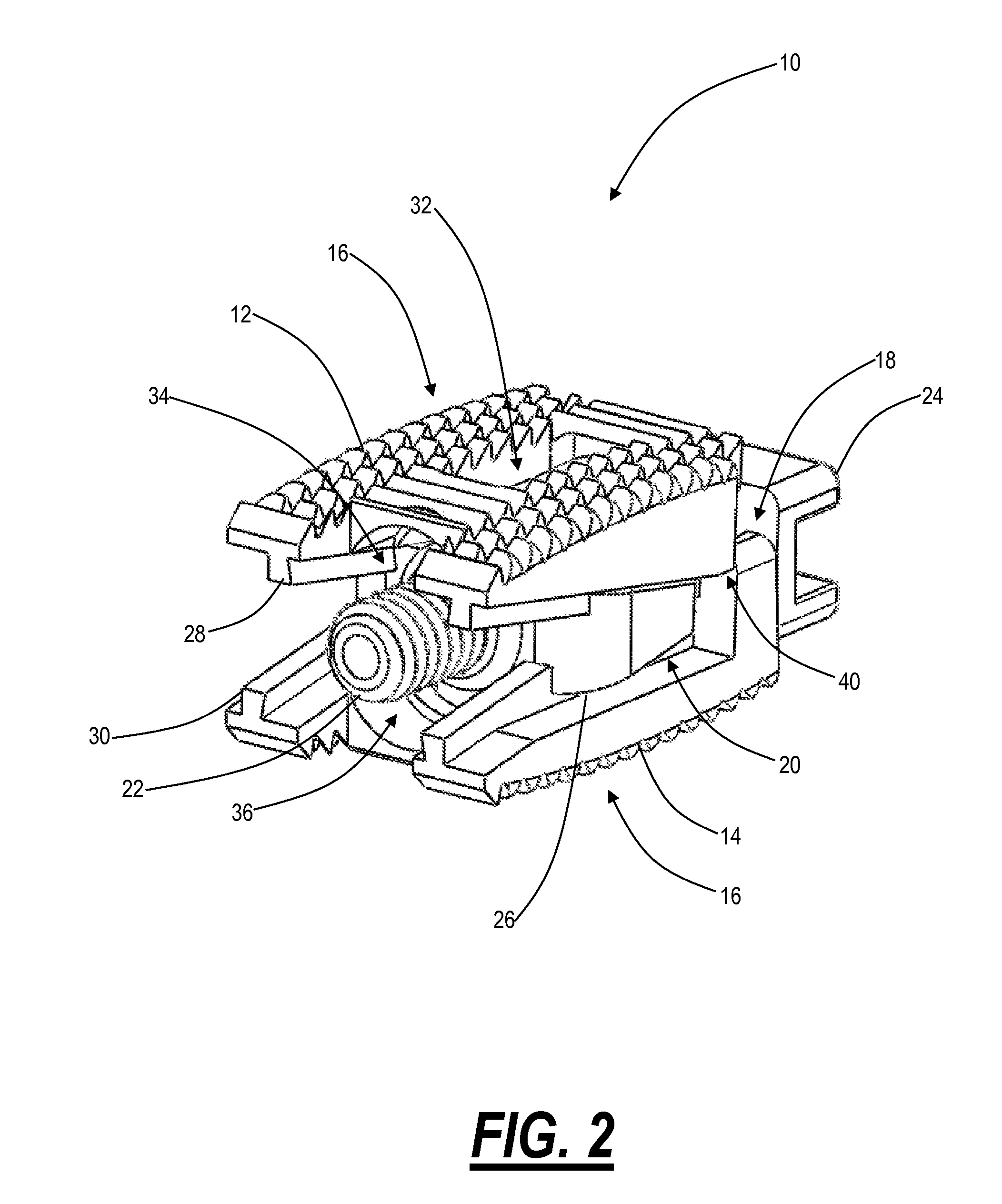
[0065]Referring to FIG. 1, in one exemplary embodiment, the present invention provides an expandable intervertebral implant 10 that is selectively disposed in the intervertebral space and deployed, thereby in-situ distracting, realigning, and / or stabilizing or fusing a portion of the spine of a patient in the treatment of injury, disease, and / or degenerative condition. The expandable intervertebral implant 10 includes a superior member 12 and an inferior member 14, each of which has a partially or substantially wedge or prismatic shape and a partially or substantially convex or other-shaped surface that is suitable for engaging the substantially concave surfaces of the associated bony superior and inferior intervertebral endplates. Optionally, the superior member 12 and the inferior member 14 are each thinner at the leading edge of the expandable intervertebral implant 10 than they are at the trailing edge of the expandable intervertebral implant 10, such that insertion into the int...


PUM


Abstract

The present invention provides an expandable intervertebral implant, including: a superior member configured to engage a superior intervertebral body; an inferior member configured to engage an inferior intervertebral body; and an expansion mechanism disposed between the superior member and the inferior member configured to selectively adjust a separation of the superior member from the inferior member; wherein the expansion mechanism includes a proximal wedge structure and a distal wedge structure that are relatively translated between the superior member and the inferior member, wherein the proximal wedge structure and the distal wedge structure are each coupled to the superior member and the inferior member by a plurality of aligned and / or staggered (i.e. nested) track structures and rail structures; and wherein a load-bearing portion of a bottom surface of the superior member is configured to mate vertically with a load-bearing portion of a top surface of the inferior member when the expansion mechanism is undeployed via conformal protruding and recessed features.

Description

CROSS-REFERENCE TO RELATED APPLICATION(S)[0001]The present patent application / patent is a continuation-in-part (CIP) of co-pending U.S. patent application Ser. No. 13 / 432,270, filed on Mar. 28, 2012, and entitled “EXPANDABLE INTERVERTEBRAL IMPLANT AND ASSOCIATED SURGICAL METHOD,” which is a continuation-in-part (CIP) of co-pending U.S. patent application Ser. No. 12 / 974,511, filed on Dec. 21, 2010, and entitled “EXPANDABLE INTERVERTEBRAL IMPLANT AND ASSOCIATED SURGICAL METHOD,” which claims the benefit of priority of U.S. Provisional Patent Application No. 61 / 293,997, filed on Jan. 11, 2010, and entitled “EXPANDABLE INTERVERTEBRAL BODY STABILIZATION DEVICES AND ASSOCIATED SURGICAL METHODS” and U.S. Provisional Patent Application No. 61 / 296,932, filed on Jan. 21, 2010, and entitled “EXPANDABLE INTERVERTEBRAL BODY STABILIZATION DEVICES AND ASSOCIATED SURGICAL METHODS,” the contents of all of which are incorporated in full by reference herein.FIELD OF THE INVENTION[0002]The present inv...

Claims


Application Information

Patent Timeline
Patent Type & Authority Patents(United States)
IPC IPC(8): A61F2/30A61F2/46A61F2/44
CPCA61F2002/30579A61F2002/30434A61F2002/4624A61F2002/30601A61F2002/30551A61F2002/30878A61F2002/30538A61F2/4611A61F2002/30387A61F2002/30616A61F2002/30827A61F2002/4627A61F2002/4623A61F2002/30281A61F2002/304A61F2002/30522A61F2002/3039A61F2002/30556A61F2002/30507A61F2/447A61F2002/30397A61F2002/30904A61F2002/30841A61F2/4603A61F2002/30433A61F2002/3055
Inventor VARELA, ARMANDO
Owner INNOVA SPINAL TECH
Learn More